
Window Flashing: Sloped Sill Pans, Shingle Laps and Weep Paths
Trace window flashing from sill pan to jambs and head. Check back dams, shingle laps and drainage outlets before siding conceals the opening.

Window flashing works when each layer carries water onto the next layer and ultimately out of the wall. For a drained, flanged window in a wood-framed wall with sheet water-resistive barrier (WRB), start with the sill pan, set the window, flash the jambs and head, then lap the upper WRB over the head flashing. Keep the pan’s exterior outlet open and make the air seal at the interior perimeter.
A sloped sill pan with a back dam and end dams gives incidental leakage a route outward. Wind-driven rain makes both that drainage route and the air-seal location important. Before siding or trim conceals the opening, check the pan corners, the direction of every lap and the final outlet. The inspection checklist below turns those checks into a record for each window.
Form the sill pan before setting the window
Window sill pan flashing collects water beneath the frame and drains it over the WRB below. Its rear upturn is the back dam; its side upturns form end dams. In the sloped detail described here, the pan falls toward the exterior while the dams contain water at the interior and sides.
Building Science Corporation’s Info-302: Pan Flashing for Exterior Wall Openings identifies a continuous waterproof surface, a back dam or positive slope, end dams and an overlap onto the lower drainage plane as the essential features. A detail combining slope and a back dam must also leave room for the window’s required support and interior seal.
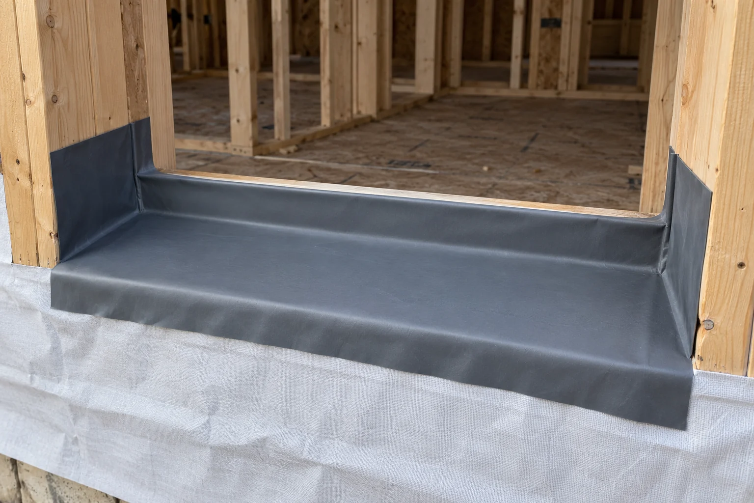
Work through the geometry before placing the window:
- Lower WRB first: establish the drainage surface beneath the opening so the pan apron can overlap its exterior face.
- Corners fully supported: press flexible flashing into the sill-to-jamb corners. Membrane stretched across a corner can tear when the window is set. Close joints in a manufactured pan using its specified joint treatment.
- Back and end dams connected: check that the rear upturn joins the side protection continuously and remains intact during installation.
- Outward drainage: follow the pan surface to its front edge. Remove debris and resolve wrinkles or obstructions that retain water.
- Window support coordinated: fit the specified shims or support system while keeping the drainage route clear. Set the window level, plumb and square over the outward-draining pan.
How high should the back dam be?
Use the height and shape in the selected pan/window installation detail. Record both the required geometry and the observed condition, including clearance to the frame and interior seal. A higher back dam changes the space available in the rough opening; it needs to fit the complete assembly.
Before applying the flashing, check compatibility among the membrane, WRB, sealant and window materials. Follow the flashing instructions for substrate preparation, primer and application conditions. These connections belong to the wider water-control system described in building envelope basics.
Install window flashing in shingle fashion
Shingle-fashion window flashing places each upper drainage layer over the layer below it. Water traveling down the wall should land on the exposed face of the next layer, rather than run behind it through a reversed lap.
The DOE/PNNL guide, Windows and Doors are Fully Flashed, describes this progression. For a flanged window installed after sheet WRB, inspect the sequence as follows:
- Prepare the WRB at the opening. Form the opening and temporarily lift the upper flap according to the WRB installation detail. Preserve the lower drainage layer that will receive the pan apron.
- Install the sill pan. Complete the outward-draining basin, back/end dams and corner treatment before setting the window. Lap its front apron over the lower WRB.
- Set and secure the window. Use the window manufacturer’s support, fastening and sealant pattern. Coordinate sealant placement with the pan’s required drainage outlet.
- Flash the jambs. Cover the side flanges and lap the jamb flashing over the sill-pan flashing. Extend the jamb treatment above the head flange as specified by the selected system.
- Flash the head and integrate the specified cap. The head flashing overlaps the jamb flashing and extends beyond it. Where the detail places a drip cap at this stage, cover its upstand with the head flashing.
- Restore the upper WRB lap. Fold the upper flap down over the head flashing and complete its cuts and seams using the WRB system’s instructions.
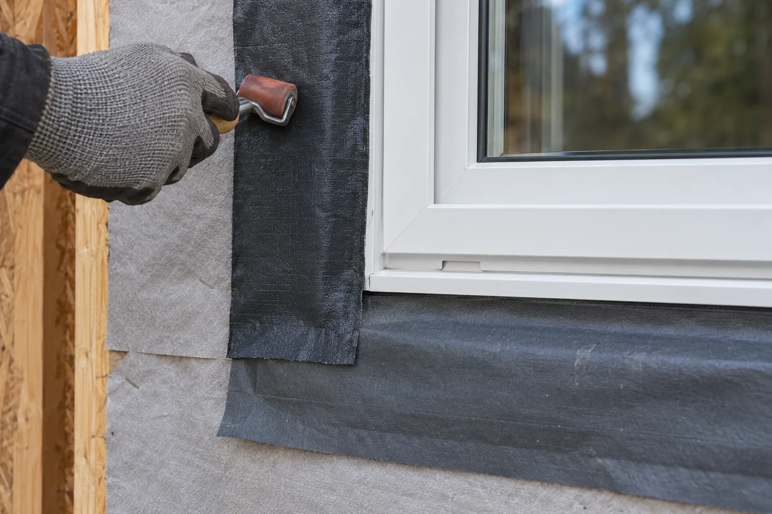
Use the specified overlap lengths for the actual flashing system. For fluid-applied WRBs or taped structural sheathing, use that system’s opening-transition detail; the sheet-WRB flap operation belongs to sheet membranes.
Head flashing and a drip cap do different jobs
Head flashing connects the top of the opening to the wall’s drainage plane. A projecting drip cap sheds water away from the top of the window or trim. Home Innovation Research Labs’ TechNote: Window and Door Flashing—Code Requirements and Best Practices treats these as distinct parts of the assembly.
Identify the cap location on the window-and-trim detail. A cap above separate head trim may be installed later than the window’s head-flashing membrane. Its back leg still needs an integrated, water-shedding connection to the layers above. Inspect that later connection before cladding covers it, and check the discharge route alongside the rainscreen wall system.
Preserve weep paths and seal air on the inside
Keep the sill pan’s discharge route clear while sealing the frame-to-opening joint toward the interior. The two locations serve different functions: the exterior portion drains water, while the interior seal connects the window to the air barrier.
Building Science Corporation’s Info-406: Air Sealing Windows explains that placing the seal toward the interior edge helps preserve drainage and reduces the pressure difference driving moisture through the outer joint. This matters when wind-driven rain reaches the opening. Water can still enter through other mechanisms, so the drainage route remains necessary.
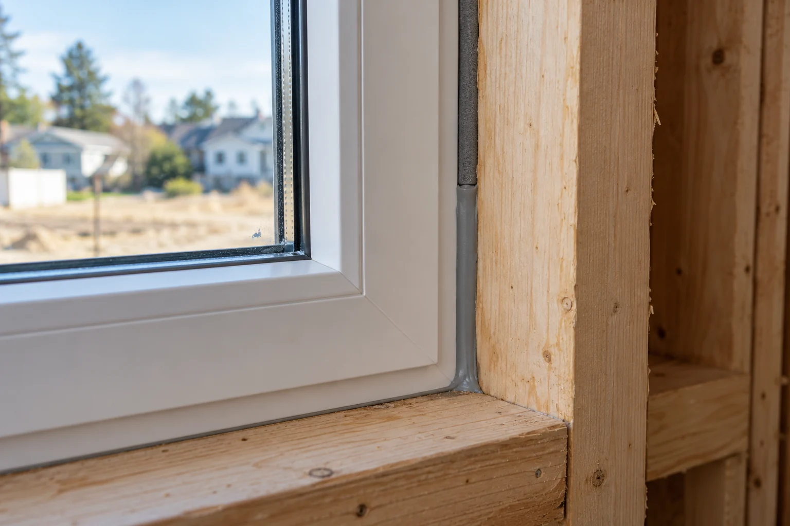
Identify these three features separately during inspection:
Swipe or scroll horizontally to view all columns →
| Feature | Where to look | What to preserve |
|---|---|---|
| Sill-pan outlet | Beneath the window, where the rough-opening pan discharges over the lower drainage plane | The open route required by the pan/window detail, including its passage past supports and trim |
| Factory frame weeps | Drain openings formed into the window frame | The manufacturer’s drainage openings, clear of sealant, paint and debris |
| Interior air seal | Room-side connection between the frame and rough opening | A continuous, flexible air-barrier connection around the perimeter |
Use a compatible air-impermeable seal, such as an appropriately detailed backer-rod-and-sealant joint or suitable low-expansion window foam. Fibrous insulation alone does not establish this air-barrier connection. Keep sealant and foam out of the pan’s drainage route.
Should the bottom window flange be caulked?
Follow the window manufacturer’s sealing pattern together with the selected drained-opening detail. The DOE/PNNL illustrated sequence leaves the sill uncaulked, and the Home Innovation TechNote describes top-and-side flange sealant with the bottom left for drainage as common practice. The installation must retain the outlet intended for that window and pan assembly.
For an existing finished window, identify the frame weeps and concealed pan detail before changing sealant. Document the water-entry pattern and have the installer establish the repair detail. Cutting an unidentified bead can interrupt another necessary seal without restoring the pan outlet.
Inspect before siding conceals the opening
Trace a continuous route from the upper WRB, over the head and jamb flashings, through the sill pan and onto the drainage plane below. DOE/PNNL recommends visually inspecting the flashing and its integration before siding is installed. Check the interior seal as a separate part of that inspection.
Use visible symptoms to choose an inspection location; then confirm the defect at the connection itself.
Swipe or scroll horizontally to view all columns →
| Observation | Inspect here | Correction to resolve before concealment |
|---|---|---|
| A membrane pocket or stretched corner | Sill-to-jamb transition and pan corners | Fit and support the corner; repair tears or joints with the specified system |
| Lower WRB overlaps the pan apron | Front edge of the sill pan | Restore the pan-over-WRB lap so discharge reaches the outside face |
| Jamb flashing disappears behind the pan flashing | Lower jamb intersection | Restore the upper-over-lower lap in the approved sequence |
| Upper WRB terminates behind head flashing | Head of the opening | Reconnect the upper drainage plane over the head treatment |
| Sealant, tape or foam bridges the intended outlet | Bottom flange, pan discharge and support locations | Resolve the obstruction using the window/pan detail while retaining required seals and support |
| Interior staining after rain | Head, jamb, sill and adjacent wall transitions | Trace the entry route before selecting a repair; the stain may be downstream of the defect |
Download the window-opening inspection checklist
Download the editable window flashing inspection checklist (CSV). Open it in a spreadsheet and save one copy per opening. It includes the detail revision, required and observed back-dam geometry, lap checks, outlet condition, interior seal, photographs and correction responsibility.
Mark each item Pass, Fix or Not visible. Use N/A only where the selected detail omits the component and record the reason. A concealed connection marked Not visible needs installation photographs or an agreed inspection opening before it can be verified. Recheck corrected areas and record the date before covering them.
For a wet-weather project, pair this opening inspection with the enclosure and drying sequence in building for rainy climates. Return to Building Materials to coordinate the window detail with the wall’s cladding, insulation and water-control layers.
Technical references: DOE/PNNL, Windows and Doors are Fully Flashed; Building Science Corporation, Info-302: Pan Flashing for Exterior Wall Openings (2013) and Info-406: Air Sealing Windows (2009); Home Innovation Research Labs, TechNote: Window and Door Flashing—Code Requirements and Best Practices (revised 2017).
Related articles
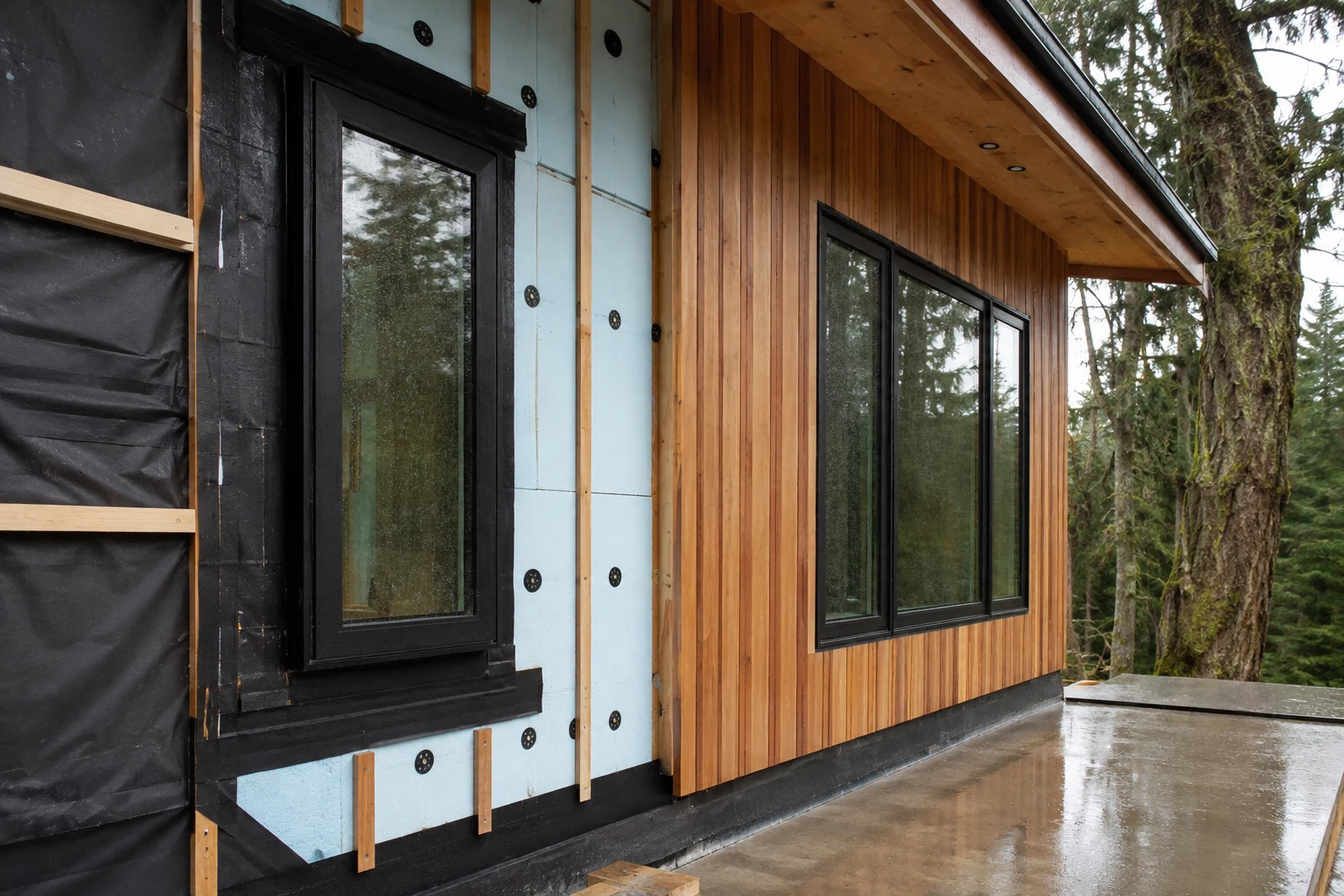
Building Envelope Basics for West Coast Projects
Trace water, air, vapor and thermal control across openings and joints; assign missing details before finishes hide paths for leaks.
Read article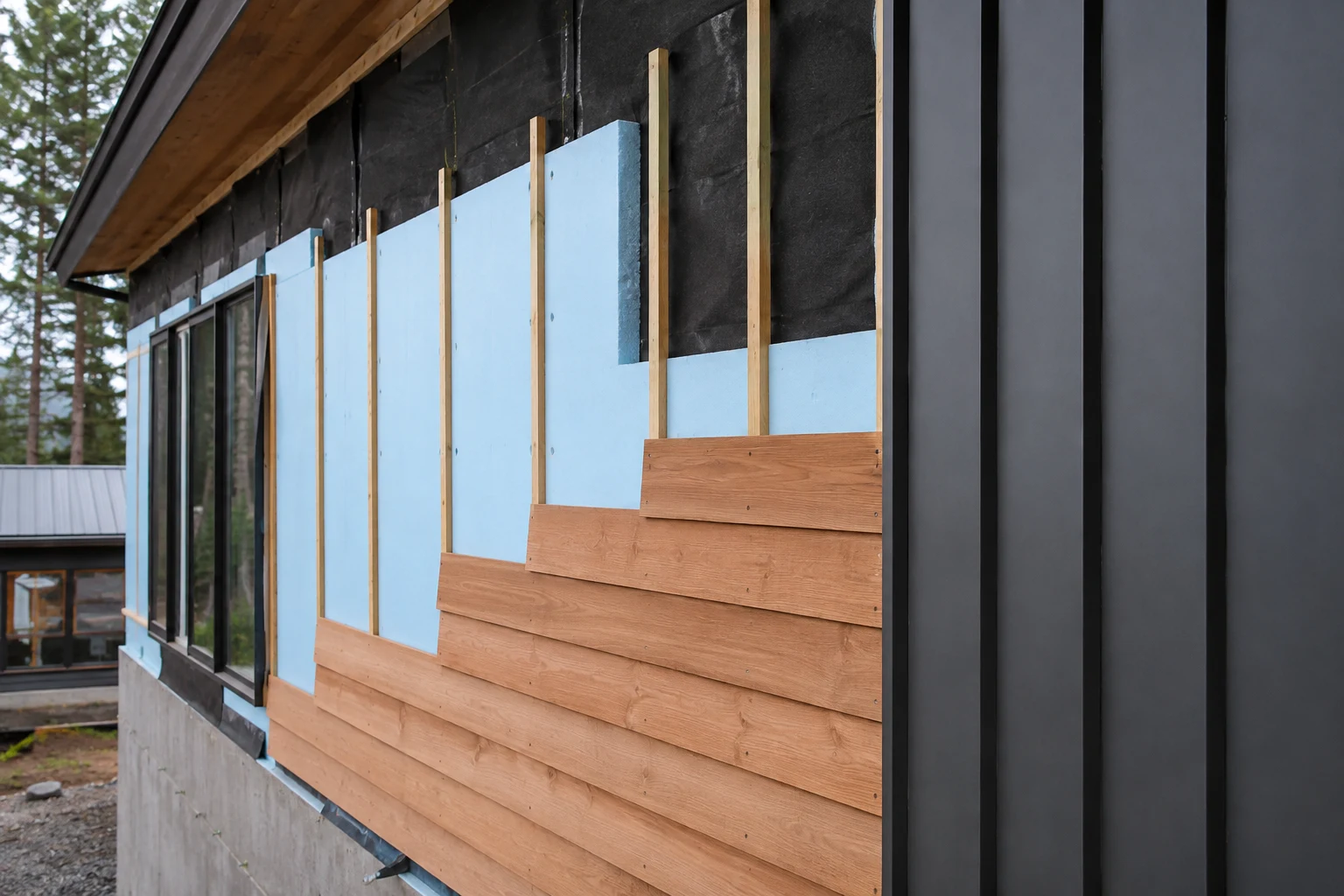
Rainscreen Wall Systems: Design and Construction Guide
Choose drained, ventilated or engineered pressure-controlled walls first; keep the selected system's drainage and ventilation outlets clear.
Read article
Building for Rainy Climates
Construction priorities for wind-driven rain, drainage, flashing, temporary protection, drying, and moisture verification in wet West Coast regions.
Read article