
Parapet Coping Installation: Review Joints and the Water Layer Beneath
Separate the metal coping cap from the waterproof membrane beneath it, and verify splice plates, miters, wall terminations, and substrates before closure.
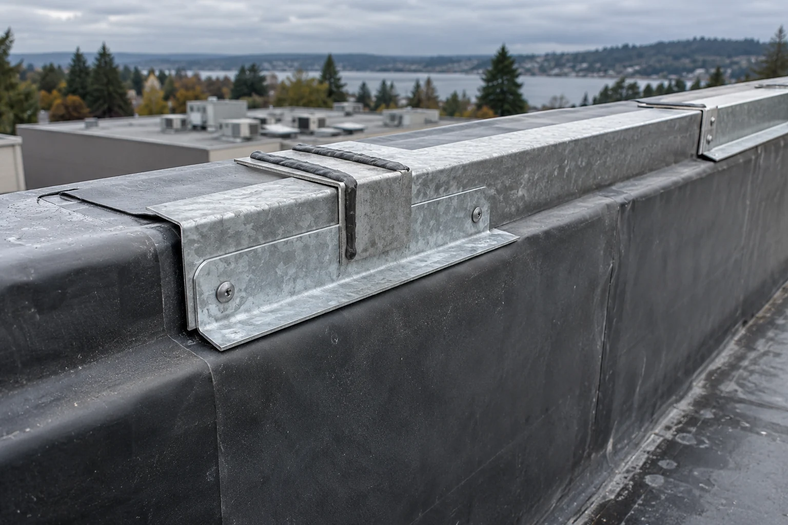
Relying on a sheet-metal coping cap alone to keep rain out of a parapet top leads to concealed leaks and framing or masonry damage because metal and stone copings leak at their joints. Before approving a parapet coping installation or snapping the metal cover onto the wall, verify that a continuous waterproof membrane covers the sloped parapet substrate beneath the coping and match every splice plate, corner miter, endcap, and wall termination to the exact manufacturer instruction sheet.
A review of parapet coping installation and parapet capping joints on a commercial or multi-family low-slope roof is an enclosure coordination check, not an interior woodworking exercise in coped baseboard trim. On a roof parapet, the metal cap sheds bulk rain and protects the roof perimeter against wind uplift, while the continuous membrane underneath serves as the primary water-control layer. In Metal-Era’s Perma-Tite Coping installation instruction (DWG # 11111-39685 Rev. E, dated November 18, 2024), each joint between 12'-0" coping covers sits over an 8" wide concealed splice plate with factory-applied dual non-curing sealant strips and requires a 3/8" space for movement over a roof membrane supplied by others, with ANSI/SPRI/FM 4435/ES-1 tested limits of 4" inside face, 6" outside face, and 16" wall width.
This guide sits under the Building Materials hub. Our building envelope basics guide identifies parapets and roof edges as priority transition locations, but it does not hold a component-level record for coping clips, splice plates, miters, or wall terminations. Use the tables below to connect the coping manufacturer’s installation drawing, the roofing contractor’s under-coping membrane detail, and the wall trade’s substrate and counterflashing scope before the cap metal conceals the top of the wall.
Swipe or scroll horizontally to view all columns →
| Review input | Source or document to check | What it resolves |
|---|---|---|
| Parapet top slope and drip edges | Building Science Corporation BSI-050 (April 17, 2012) and project roof-edge section | Whether water drains inward toward the roof and drips clear of both wall faces |
| Under-coping waterproof membrane | BSI-050 Figure 4 and coping instruction prerequisite (such as Metal-Era DWG # 11111-39685 Rev. E, Page 5) |
Whether a continuous membrane wraps the substrate before clips and splice plates are fastened |
| Tested face and wall dimensions | Manufacturer’s current installation sheet and ANSI/SPRI/FM 4435/ES-1 listing |
Whether the project’s wall width and inside/outside face heights stay inside the tested boundary |
| Substrate fastener and clip schedule | Manufacturer substrate table and straight-run clip spacing chart (11/18/24 Page 4) |
Which top and face fasteners and clip centers (4'-0", 3'-0", or 2'-0" O.C.) apply to the wall width |
| Splice plates, miters, and endcaps | Manufacturer step-by-step sequence (11/18/24 Pages 5 to 7) |
Whether corner and end accessories are installed first with the specified 3/8" joint space |
| Coping-to-wall termination | Building Enclosure termination detail (February 3, 2011) and manufacturer endwall steps | Who supplies the wall pre-flashing, counterflashing, saddle flashing, fasteners, and sealant |
How do the metal coping cap and the membrane beneath it divide water control?
The metal coping cap is a secondary weather hood and wind-edge restraint; the membrane underneath the coping is the primary water-control layer across the top of the parapet. In Building Science Corporation’s BSI-050: Parapets—Where Roofs Meet Walls, dated April 17, 2012 and authored by Joseph Lstiburek, parapets protect roof edges from wind-induced vortices and pressure differences (citing H.J. Leutheusser’s 1964 University of Toronto research). When rainwater hits the top of the wall, however, BSI-050 states directly that metal and stone copings leak at joints.
To keep water out of the parapet assembly, BSI-050 Figure 4 and Photograph 1 set three physical requirements at the top of the wall:
- Slope the top of the parapet inward toward the roof so runoff drains onto the roof assembly rather than staining the exterior building facade.
- Install a continuous waterproof membrane under the coping across the top of the wall.
- Provide drip edges on both the front (exterior) and back (interior roof side) of the coping so water drips free of the vertical wall surfaces instead of tracking back to stain the facade, as shown in BSI-050 Photograph 2.
Beneath that cap, BSI-050 Figure 5 adapts Max Baker’s 1980 book Roofs into four continuity requirements (“Baker Principles”): connect the roof water-control layer to the wall water-control layer, the roof air-control layer to the wall air-control layer, the roof vapor-control layer to the wall vapor-control layer, and the roof thermal-control layer to the wall thermal-control layer. BSI-050 Figure 6 (“Problem Parapet”) shows what happens when those layers stop at the framing top: no membrane sits under the parapet flashing, air leaks between the roof and parapet framing, and thermal bridging runs through the top of the wall.
Manufacturer coping instructions reflect the same division of responsibility. In Metal-Era’s Installation Instruction for Perma-Tite Coping (DWG # 11111-39685 Rev. E, dated November 18, 2024), the cross-sections on Page 3 label the underlying layer ROOF MEMBRANE (BY OTHERS). Page 5 adds an installation prerequisite before Step 1: position the roof membrane on top of the wall covering the treated wood nailer or substrate completely, and allow a 1/2" minimum excess membrane beyond the nailer where applicable.
Takeaway: A coping submittal never closes the waterproofing check by itself; require a signed roof-to-wall detail showing the continuous membrane under the coping and its lap onto the wall and roof control layers before anchor clips are attached.
During wet-season reroofing or facade work on the West Coast, use the rainy-climate construction guide to review temporary weather protection while parapet blocking and membranes are exposed before the metal cover is snapped on.
What must be verified on the manufacturer sheet for clips, fasteners, and splice joints?
Check the exact product series, drawing number, revision date, tested dimension boundary, substrate fastener pairing, clip spacing, and joint gap on the manufacturer’s installation sheet rather than relying on a catalog brochure or a rule of thumb. On Metal-Era’s general product page (metalera.com/products/types/coping), the company groups multiple lines under one category, including Perma-Tite Coping (Tapered, Flat, Existing Slope, Continuous Cleat, Cantilever, Double Tapered, and Arched), Edge Systems One, and Creative Design Series. The catalog overview does not list clip spacing, fastener gauges, or joint gaps. Those details live on the specific installation drawing.
In the opened instruction sheet for Metal-Era Perma-Tite Coping (DWG # 11111-39685 Rev. E, dated November 18, 2024), Page 1 and Page 3 separate two sets of numbers that reviewers often confuse: fabrication range versus ANSI/SPRI/FM 4435/ES-1 tested limits.
Swipe or scroll horizontally to view all columns →
Parameter on DWG # 11111-39685 Rev. E (11/18/24) |
Stated fabrication or component value | Stated ANSI/SPRI/FM 4435/ES-1 tested limit or condition |
What the project reviewer must verify |
|---|---|---|---|
| Inside face dimension | Min. 2-1/4", Max. 12" |
Max. (tested) 4" |
Actual inside face height on project drawings (___) |
| Outside face dimension | Min. 3", Max. 12" (with 5/8" kick/edge) |
Max. (tested) 6" |
Actual outside face height on project drawings (___) |
| Actual wall size (width) | Min. 3-1/2", Max. 39-7/8" (plus 3/8" space for wall variations) |
Max. (tested) 16" |
Actual parapet width including sheathing and membrane build-up (___) |
| Coping cover length and joint space | 12'-0" straight lengths (4'-0" for arched coping) |
Leave a 3/8" space at each joint (Step 17; Radius Step 4; Arched Step 3) |
Joint layout and field-cut edge preparation (___) |
| Concealed splice plate | 8" wide concealed splice plate at each joint |
Factory-applied dual non-curing sealant strips; release paper removed at install | Whether splice plates match the ordered profile and radius (___) |
| Anchor clip (Tapered, Flat, Existing Slope) | 12" wide 20 ga. galvanized anchor clips |
Spacing determined by manufacturer by wall size: 4'-0" O.C. (0" thru 12"), 3'-0" O.C. (12-1/16" thru 24"), 2'-0" O.C. (24-1/16" thru 39-7/8") |
Wall width bracket, or double spring clips for radius coping (___) |
| Wood substrate fasteners | Top: #10 x 1-1/2" stainless steel screw; Face: #14 x 1-1/2" Profiler |
Provided by manufacturer (except Arched Coping, where fasteners are BY OTHERS) |
Wood nailer thickness, treatment chemistry, and hole position (___) |
| Masonry substrate fasteners | Top: 1/4" x 1-1/4" Tapcon; Face: #14 x 1-1/2" Profiler |
Provided by manufacturer; locate in third full hole from bend and drip per Page 4 | Masonry condition at top edge and fastener embedment (___) |
| Metal substrate fasteners | Top: #12-14 x 1" Tek3; Face: #14 x 1-1/2" Profiler |
Provided by manufacturer; do not over-tighten | Metal gauge and framing layout beneath membrane (___) |
Notice how the 11/18/24 instruction sheet handles wall widths and fastener placement. If a commercial parapet is 20" wide, it falls inside the sheet’s 12-1/16" THRU 24" fabrication bracket (which calls for 3'-0" O.C. anchor clip spacing and the wide-wall clip detail for walls greater than 14"), but it exceeds the 16" maximum tested wall width printed under the ANSI/SPRI/FM 4435/ES-1 approval note on Page 1 and Page 3. Our How We Review Materials page explains why declared product dimensions and tested assembly limits must stay in separate columns. When a wall exceeds the tested dimension on the standard sheet, leave the wind-compliance cell open until the manufacturer or project engineer supplies documentation for that specific geometry.
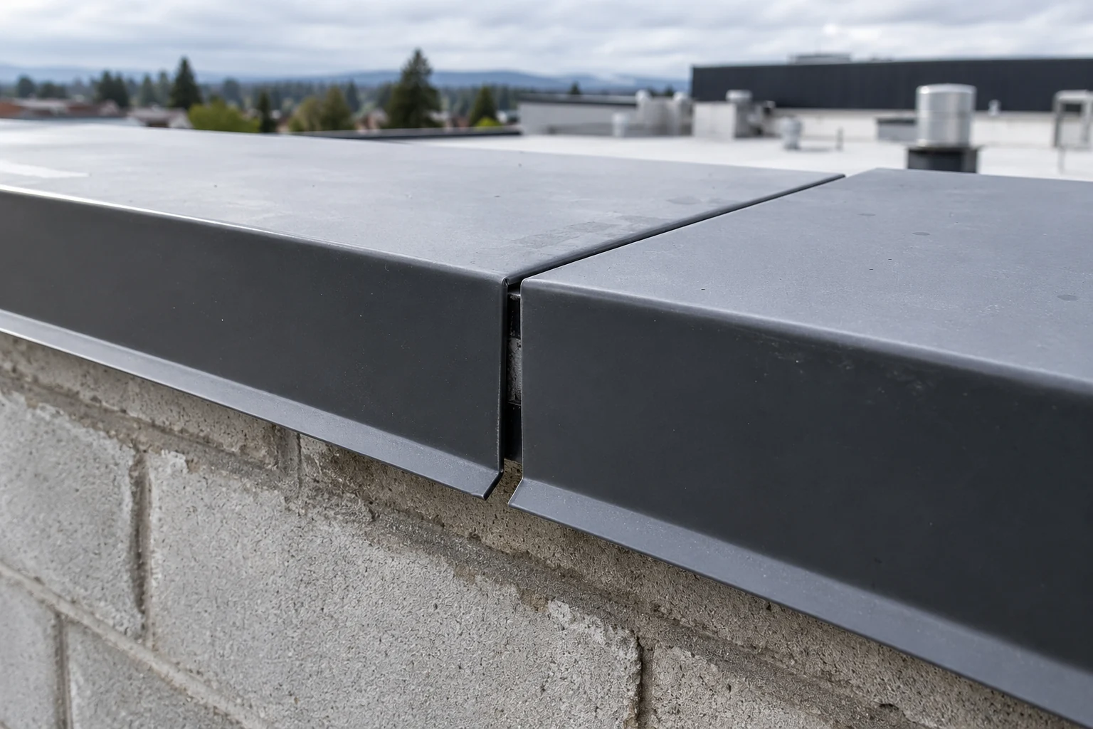
Page 4 of the 11/18/24 Metal-Era manual also specifies exact fastener hole locations on the anchor clip: locate the top fastener in the third full hole from the bend on the inside (or first full hole from the bend on the outside as diagrammed for the appropriate substrate), locate the face fastener in the third full hole from the drip on both inside and outside faces, and do not over-tighten. On coastal West Coast roofs exposed to marine salt spray, check fastener and clip metal compatibility alongside the coastal construction guide before accepting standard galvanized components near the shoreline.
Why must corner miters, endcaps, and wall terminations be installed before straight runs?
On a snap-on parapet coping system, corners, endcaps, and endwall flashings establish the fixed reference points and concealed splice engagements that the straight 12'-0" sections hook over last. Metal-Era’s 11/18/24 instruction sheet prints CAUTION: INSTALL ACCESSORIES FIRST! on Page 5 and structures the installation sequence around that rule:
- Corner support clips and miters (Steps 1 to 3): Fasten galvanized corner support clips to the wall first. Remove the release paper from the splice plate sealant strips, center an
8"splice plate on an anchor clip, slide the splice plate and anchor clip assemblies halfway into each end of the corner miter, position the corner assembly on the parapet, and fasten at the exposed edge of the anchor clips per the Page 4 substrate table. - Endcaps (Steps 4 to 6): Fasten galvanized anchor clips at the termination end, remove release paper from the top of the factory-applied sealant strips, place a splice plate onto the second anchor clip, hook the outside face of the endcap over the anchor clips, rotate it into place, and press downward on the rear leg until the snap-lock engages.
- Endwall flashing (Steps 7 to 10): The manual shows two distinct details where a parapet meets a rising wall: an Endwall Flashing Coping Version (Steps 7 and 8) and a
12"Endwall Flashing Splice Version (Steps 9 and 10). In both versions, the wall fasteners and the non-curing sealant applied to the caulk cup atop the3"vertical flange are marked(BY OTHERS). - Straight anchor clips, splice plates, and coping covers (Steps 11, 15, 16, and 17): Fasten straight-run anchor clips at the Page 4 centers, place a splice plate onto each joint anchor clip with release paper removed, hook the outside face of each
12'-0"coping cover over the clips, and press the rear leg down until snap-lock occurs. Field-cut the closing straight section with a fine-tooth hacksaw, snips, or cut-off wheel for a clean edge, leave a3/8"space at each joint, and remove the plastic protective film immediately.
Where a lower parapet coping terminates against a taller structural wall, the coping manufacturer’s endwall flange is only part of the enclosure interface. In Building Enclosure’s technical article Roofing Detail: Coping-to-Wall Termination, published February 3, 2011, the author notes that the most common mistake at this intersection is allowing the metal coping to butt directly against the structural wall without termination metal. Omitting the termination flashing leaves an opening at the top of the coping where water runs between the parapet wall and the structural wall while the two components move differentially.
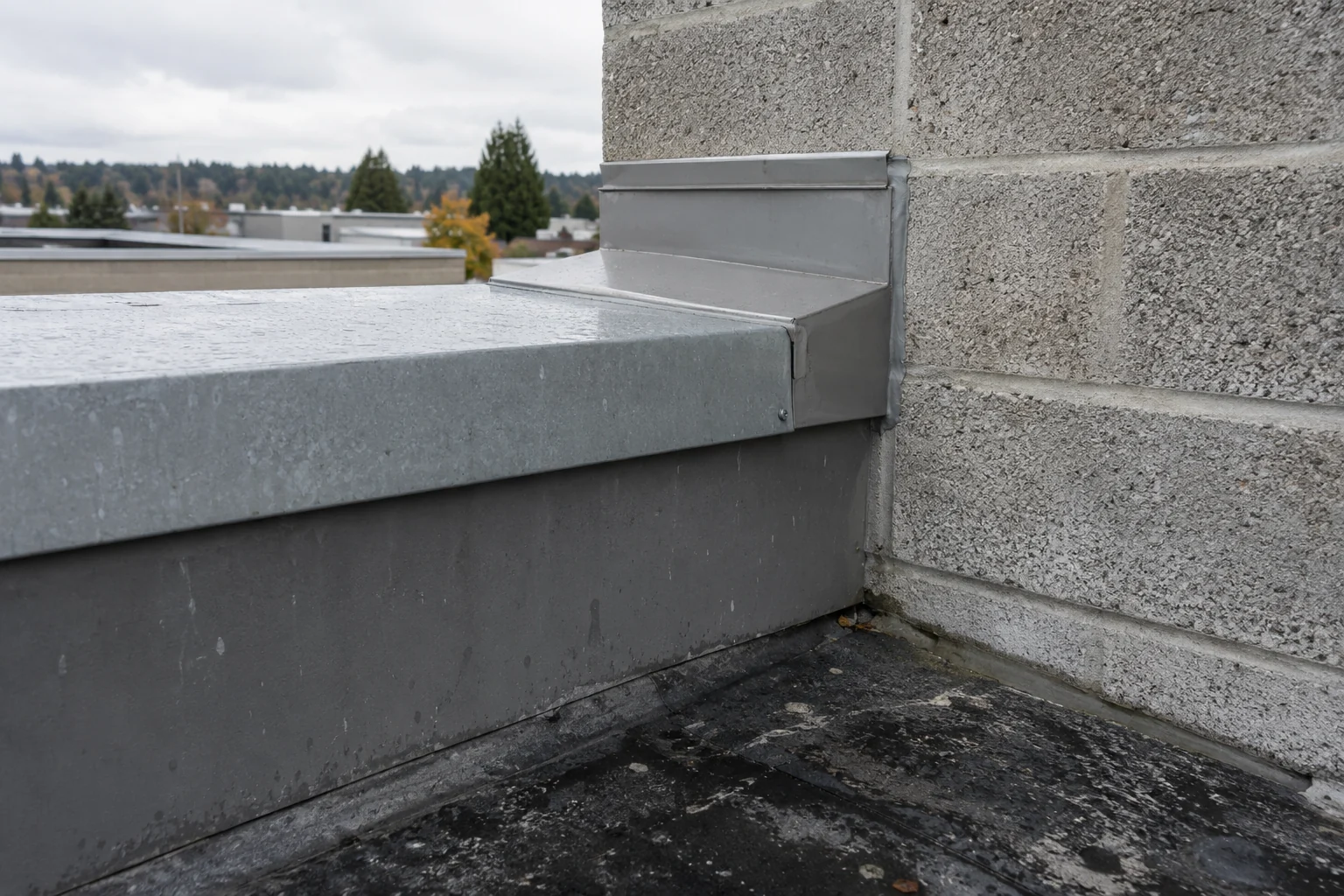
The 2011 Building Enclosure detail sequences five layers at that wall intersection:
- Pre-flash the coping-to-wall intersection with membrane flashing (such as self-adhering membrane) before sheet-metal saddle installation (Note 6), attaching the top of the membrane wall flashing at approximately
6" O.C.(Note 2). - Adhere metal wall flashing to the structural wall so it laps over the parapet wall before the coping is installed.
- Terminate the top of the metal wall flashing with a counterflashing that is either surface-mounted or set into a reglet cut into the wall.
- Install the
ANSI/SPRI ES-1compliant metal coping over the completed wall flashing (with continuous cleats recommended in Note 4 when the flashing face exceeds3"or in local high-wind zones). - Set a prefabricated sheet-metal saddle flashing over the junction of the structural wall and parapet wall in two continuous beads of sealant, and apply a continuous bead of sealant along the top of the counterflashing and the seams of the saddle flashing.
Note 5 of that Building Enclosure detail highlights the contract gap that causes field disputes: certain components depicted in the detail may not be provided by the roofing contractor. When Metal-Era marks endwall fasteners and caulk-cup sealant (BY OTHERS) and the roofing detail notes that counterflashing or reglets may fall outside the roofer’s scope, the submittal review must name the exact trade responsible for each piece before work starts. If water has already bypassed an unsealed wall termination, use the moisture-control guide to track interior wall and ceiling moisture paths before closing repairs.
Copy the parapet coping joint and membrane review record
Copy the table below once for each parapet run or roof-to-wall elevation under review. The source column summarizes what the opened documents state; the project cells (___) start blank so your team can record actual drawing numbers, product revisions, field observations, and trade ownership. Do not fill a project cell until the matching submittal sheet or field photograph is in hand.
Swipe or scroll horizontally to view all columns →
| Location or check item | What the opened source states | Project drawing, product sheet, and revision | Field or submittal finding (___ if unverified) |
Trade owner and resolution date |
|---|---|---|---|---|
| Parapet top slope and drip edges | BSI-050 (04/17/2012), Figure 4: slope parapet top inward toward roof; provide front and back drip edges to prevent facade staining. | Drawing/detail: ___ |
Slope direction and drip-edge projection: ___ |
___ |
| Under-coping waterproof membrane | BSI-050 Figure 4: continuous waterproof membrane under coping. Metal-Era 11/18/24 Page 5: roof membrane (BY OTHERS) covers treated wood nailer/substrate completely with 1/2" min. excess beyond nailer. |
Membrane product sheet and lap detail: ___ |
Membrane continuity over top nailer and connection to wall/roof air and water barriers: ___ |
___ |
Coping model, version, and ES-1 boundary |
Metal-Era DWG # 11111-39685 Rev. E (11/18/24), Pages 1 and 3: Tapered, Flat, or Existing Slope; ANSI/SPRI/FM 4435/ES-1 max. tested dimensions 4" inside face, 6" outside face, 16" wall width. |
Manufacturer sheet, model, and revision: ___ |
Project wall width (___), inside face (___), outside face (___), and whether dimensions sit within tested limits: ___ |
___ |
| Substrate and fastener pairing | Metal-Era 11/18/24 Page 4: Wood (#10 x 1-1/2" SS top, #14 x 1-1/2" Profiler face); Masonry (1/4" x 1-1/4" Tapcon top, #14 x 1-1/2" Profiler face); Metal (#12-14 x 1" Tek3 top, #14 x 1-1/2" Profiler face). Arched coping fasteners (BY OTHERS). |
Substrate type and fastener specification: ___ |
Verified substrate condition, preservative treatment compatibility, and third-hole fastener placement: ___ |
___ |
| Anchor clip width and spacing | Metal-Era 11/18/24 Pages 3 and 4: 12" wide 20 ga. galv. clips at 4'-0" O.C. (0" to 12" wall), 3'-0" O.C. (12-1/16" to 24" wall), 2'-0" O.C. (24-1/16" to 39-7/8" wall); double spring clips on radius coping. |
Clip layout drawing: ___ |
Measured clip spacing on parapet (___) and wide-wall (>14") clip detail if applicable: ___ |
___ |
| Corner miters and endcaps (installed first) | Metal-Era 11/18/24 Page 5, Steps 1 to 6: install corner support clips, center 8" splice plates on anchor clips halfway into each miter end, peel sealant release paper, and install miters and endcaps before straight runs. |
Corner/endcap accessory submittal: ___ |
Confirmation that miters and endcaps were anchored and sealed before straight covers: ___ |
___ |
Straight splice joints and 3/8" gap |
Metal-Era 11/18/24 Pages 3, 6, and 7 (Steps 15 to 17): 8" wide concealed splice plate with dual non-curing sealant strips centered on clip at each joint; leave 3/8" space between 12'-0" covers; remove film immediately. |
Joint detail reference: ___ |
Release paper removed, 3/8" thermal gap verified, cut edges clean, protective film removed: ___ |
___ |
| Coping-to-wall termination and saddle flashing | Building Enclosure (02/03/2011) and Metal-Era Steps 7 to 10: membrane pre-flashing (6" O.C. top attachment), wall flashing, reglet/surface counterflashing, saddle flashing in dual sealant beads, and caulk cup sealant/fasteners (BY OTHERS). |
Wall termination detail number: ___ |
Assigned installer for pre-flashing, reglet/counterflashing, saddle flashing, and (BY OTHERS) fasteners/sealant: ___ |
___ |
Keep this completed table with the project shop drawings, the exact revision of the coping manufacturer’s installation manual, and dated field photographs taken after the under-coping membrane and anchor clips are installed but before the 12'-0" coping covers hide the substrate. If the contractor proposes a different coping manufacturer, a shop-fabricated continuous cleat, or a stone parapet cap, replace the second column with the figures from that system’s approved submittal rather than carrying Metal-Era’s numbers across products.
Common questions
Does a concealed splice plate with sealant strips eliminate the need for a membrane under the coping?
No. Building Science Corporation’s BSI-050 (April 17, 2012) states that metal and stone copings leak at joints and requires a continuous waterproof membrane under the coping across an inward-sloped parapet top. Metal-Era’s Perma-Tite Coping instruction (DWG # 11111-39685 Rev. E, dated November 18, 2024) likewise shows ROOF MEMBRANE (BY OTHERS) under its 8" dual-sealant splice plates and requires the membrane to cover the nailer or substrate completely before clip installation.
Does an ANSI/SPRI/FM 4435/ES-1 label on an instruction sheet cover every wall width the manufacturer can bend?
No. On Metal-Era’s 11/18/24 Perma-Tite Coping sheet, Page 3 shows fabrication dimensions up to a 12" inside face, 12" outside face, and 39-7/8" wall width, while the ANSI/SPRI/FM 4435/ES-1 approval note on Pages 1 and 3 specifies maximum tested dimensions of 4" inside face, 6" outside face, and 16" wall width. Always compare your project’s actual wall width and leg heights against the tested limits printed on the submittal.
Why does a coping-to-wall termination leak even when the straight coping joints are tight?
In Building Enclosure’s February 3, 2011 termination detail, butting a metal coping directly against a higher structural wall without termination metal leaves an open gap at the top of the coping where water enters between the parapet and the structural wall. Closing that intersection requires pre-flashing membrane, wall flashing, counterflashing (surface-mounted or in a reglet), and a sheet-metal saddle flashing set in two continuous beads of sealant.
Who provides the fasteners and sealant at an endwall flashing or arched coping cap?
That depends on the exact component step in the manufacturer’s manual. In Metal-Era’s 11/18/24 Perma-Tite instruction sheet, straight-run wood, masonry, and metal fasteners are provided by the manufacturer (Page 4), whereas endwall flashing fasteners and caulk-cup non-curing sealant (Page 6, Steps 7 to 9) and arched coping top fasteners and sealant (Page 8, Steps 1 to 3) are explicitly marked (BY OTHERS).
Scope and source dates
This guide was compiled from three primary technical sources reviewed on October 17, 2026, together with US Google autocomplete (autocomplete-parapet.json) and organic search snapshots (serp-parapet-coping-installation.json) captured on October 11, 2026:
- Building Science Corporation, BSI-050: Parapets—Where Roofs Meet Walls, by Joseph Lstiburek, effective April 17, 2012 (citing H.J. Leutheusser, 1964, and Max Baker, Roofs, 1980). Used for parapet water-management principles (inward slope, continuous membrane beneath leaking coping joints, front and back drip edges) and four-layer roof-to-wall control continuity.
- Metal-Era LLC, Installation Instruction for Perma-Tite Coping,
DWG # 11111-39685, Revision E, dated November 18, 2024 (ME_C_Perma-Tite-Coping_All-Versions_Install_11111-39685.pdf), and the Metal-Era Coping catalog overview (metalera.com/products/types/coping, retrieved October 11, 2026). Used as a bounded, named manufacturer example for tested versus fabricated dimensions, substrate fastener schedules, anchor clip spacing by wall width,8"concealed splice plates,3/8"joint spacing, andPROVIDEDversusBY OTHERSaccessory rules. - Building Enclosure, Roofing Detail: Coping-to-Wall Termination, published February 3, 2011. Used for the multi-layer sequence at a coping-to-structural-wall intersection and Note 5’s warning that certain depicted components may fall outside the roofing contractor’s scope.
These sources do not establish the current building code edition, wind-speed map, or corrosion zone adopted at a specific California, Oregon, or Washington project address. The review tables and rooftop photographs are editorial tools, not engineering calculations or construction drawings. Verify project wind-uplift pressures, substrate attachment, and trade scope with the project architect, structural engineer, and local building authority.
Related articles
Building Envelope Basics for West Coast Projects
Trace water, air, vapor and thermal control across openings and joints; assign missing details before finishes hide paths for leaks.
Read article
Moisture Control in Buildings: Design, Construction, and Maintenance
Stop the water source before rebuilding. Trace its path, measure affected materials and document project-specific acceptance before closure.
Read article
Coastal Construction: Corrosion, Wind, Rain, and Maintenance
Map salt, rain, wind and flood exposure before selecting materials; verify connections and maintenance access before concealing work.
Read article