
Deck Ledger Flashing Detail: A Rain and Coastal Review Record
Review the ledger water path, treated-wood and metal compatibility, and hidden damage. Copy a record for photos, product documents and closure decisions.
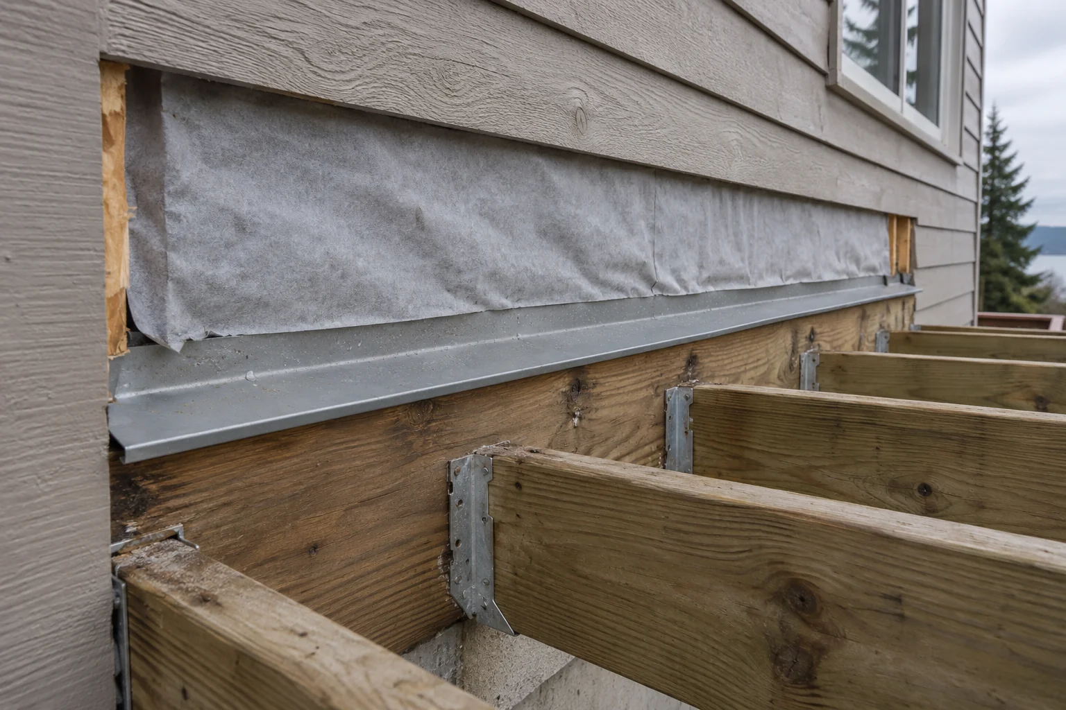
Water behind a deck ledger can damage the house framing that carries the connection. Review the deck ledger flashing detail by tracing drainage from the wall above, across the ledger and back outside, then match the wood treatment, flashing, connectors and fasteners to their actual product documents.
Keep the water path and the material compatibility record together before the ledger connection is concealed. The tables below help an owner, contractor and designer record what is known, what remains hidden and who must resolve it for a rainy or coastal residential project. They do not provide a structural attachment design or a bolt-spacing schedule.
Swipe or scroll horizontally to view all columns →
| Review input | Where it comes from | What it resolves |
|---|---|---|
| Wall water-control layer | Existing assembly investigation and project drawings | Which layer must connect to the flashing |
| Lumber treatment | Treatment tag or supplier documentation | Chemical contact conditions for metals |
| Metal and membrane identities | Exact product sheets, including coatings | Whether the proposed interfaces are supported |
| Rain and salt exposure | Site observations and designer’s assessment | Which service conditions the supplier must consider |
| Existing connection condition | Qualified inspection where deterioration is suspected | Whether the work includes framing or connection repair |
Trace the water path before choosing a tape
The ledger is the horizontal member at the deck-to-house connection. Building Science Corporation’s Information Sheet 304 explains how a ledger can interrupt wall drainage and direct water toward fastener penetrations. A strip visible above the ledger tells you little unless its connection to the wall drainage plane is known.
For the sheet’s separate housewrap or building-paper assembly, the water-control layer above overlaps the flashing; the membrane behind the ledger overlaps the drainage layer below. Its other example uses taped insulating sheathing as the drainage plane. Those are different interfaces. Ask the designer to identify which assembly the project actually has and supply the matching transition detail.
Use the drawing and the accessible assembly to answer these questions:
- Where does water traveling behind the cladding meet the ledger flashing?
- Does that connection direct water outward, or leave an edge where it can run behind the flashing?
- Where does water below the ledger return to the exterior?
- What happens at each end, splice and interruption, including a nearby door threshold?
- Can the intended exit remain open after siding, trim and deck boards are installed?
Record a photograph reference for each answer. If an existing wall’s water-control layer cannot be identified, mark that item Unknown / investigate and have the project team resolve access and repair scope. A bead of sealant on an exposed edge does not document the concealed laps.
The rainy-climate construction guide provides the wider drainage and drying review. This record follows one connection through that water path.
Resolve existing damage before covering the connection
For an existing deck, request an assessment of the ledger, the house framing receiving it, the sheathing and the connection hardware. Record staining, deteriorated edges, displaced flashing, debris and visible corrosion as observations; leave the diagnosis and repair scope to the qualified reviewer.
The American Wood Council’s DCA6 residential deck guide, under “Ledger Attachment Requirements,” requires verification that the house band joist can support the deck. Where that cannot be verified or conditions differ from its details, the guide directs the project outside that prescriptive attachment route. Flashing work alone cannot supply that verification.
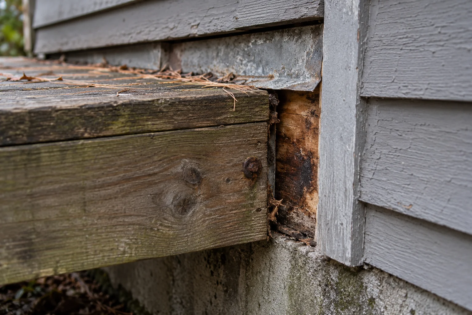
Simpson Strong-Tie’s general corrosion guidance distinguishes visible corrosion from an established loss of capacity. It calls for a qualified engineer or inspector when significant corrosion is apparent or suspected. A rust photograph cannot establish the remaining strength of the fastener or the wood behind it.
Our suggested handoff is a location-marked set of observations plus a written question: Does this area require access, repair or replacement before the water-control work proceeds? Do not loosen a load-bearing ledger to obtain a better photograph; access and any temporary support belong in the contractor’s and designer’s work plan.
Match each material to a document
“Pressure treated,” “galvanized” and “flashing tape” leave important fields unanswered. Simpson’s general guidance asks the wood supplier for the treatment chemical and retention, species group and AWPA use category. Keep that information with the hardware and flashing documents, rather than selecting a coating from the lumber’s color.
In its wood connector and fastener guidance, Simpson distinguishes wet, elevated, uncertain and ocean/waterfront service. Salt air belongs in the exposure assessment; the company also directs readers to product-specific information. Do not infer a coastal approval or a service-life guarantee from a generic material name. Use the coastal construction guide to record the broader site exposure.
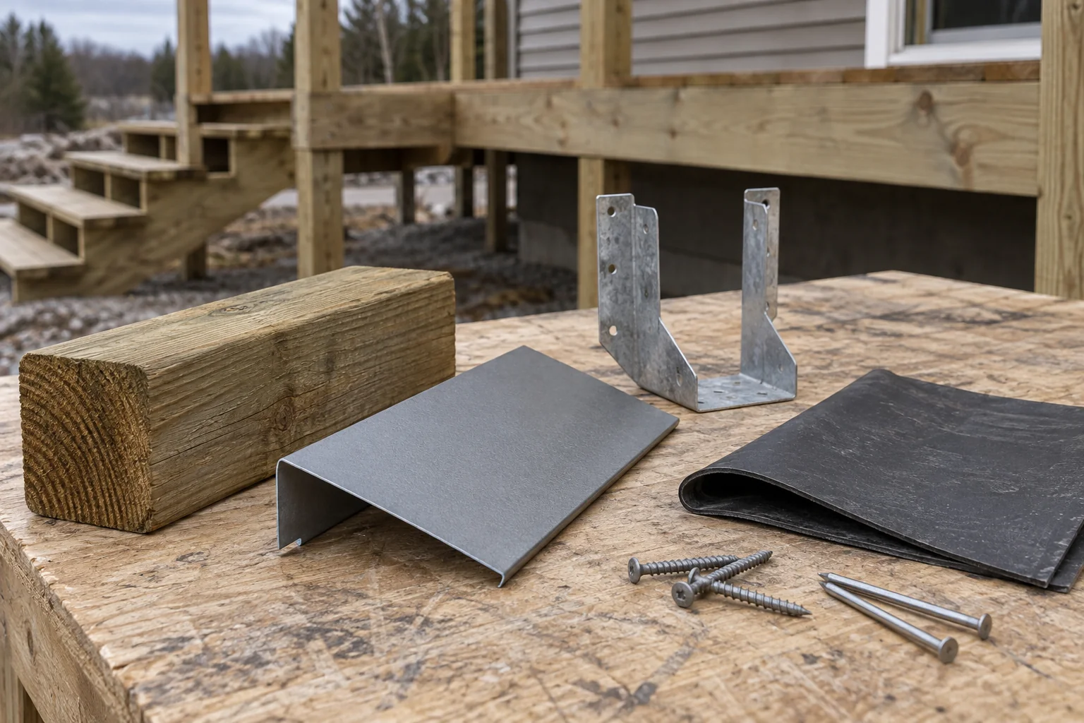
Copy the following compatibility record. The last column starts blank because none of these project products has been identified here.
Swipe or scroll horizontally to view all columns →
| Interface or condition | What the opened source supports | Document to obtain for this project | Project finding / unresolved item |
|---|---|---|---|
| Treated lumber touching flashing | AWC DCA6, minimum requirement 11, cautions against direct aluminum contact with copper-containing preservative treatments. | Treatment identification; exact flashing material/coating and allowed contact conditions. | ___ |
| Wood touching connector and fastener | Simpson general guidance makes treatment chemistry and retention part of corrosion review. | Lumber supplier information and current hardware instructions covering that treatment. | ___ |
| Fastener touching connector | Simpson general guidance identifies dissimilar-metal contact in moisture as a corrosion concern. | Specified connector and its permitted fastener material/coating; confirm them together. | ___ |
| Salt air or persistent wetting | Simpson’s service descriptions separate these conditions from a generic dry interior use. | Site exposure assessment and manufacturer’s recommendation for the exact hardware. | ___ |
| Membrane touching wood, flashing or WRB | BSC Sheet 304 shows membrane integration; its drawing does not approve every adhesive/substrate pairing. | Current membrane and WRB instructions covering the actual surfaces, preparation and transitions. | ___ |
| Barrier beneath connector versus fastener through wood | Simpson’s barrier FAQ says the barrier does not protect fasteners penetrating into the wood. | Separate fastener specification; applicable barrier-system instructions. | ___ |
| Proposed membrane and stainless hardware | Simpson’s FAQ specifically says not to use Grace Vycor Deck Protector with stainless connectors and fasteners. This is a named-system caution. | Current documents or written manufacturer clarification for the actual proposed combination. | ___ |
The final two rows come from Simpson’s Pressure-Treated Wood with Barrier Membranes FAQ. The FAQ describes a particular tested barrier and does not establish equal performance for arbitrary tapes. Its legacy product references are a reason to confirm the current system documents before specifying a combination, rather than treating the FAQ as a shopping list.
This also separates two questions often bundled into “deck ledger flashing membrane”: whether a membrane makes the specified water-control transition, and whether it is an accepted barrier at a particular wood-to-metal interface. Evidence for one purpose does not automatically answer the other.
Keep a record before concealment
Use this suggested record for each distinct ledger location. Insert the drawing reference and document revision as well as the product name. A photograph should identify the location and stage; the finished deck surface alone cannot show every concealed interface.
Swipe or scroll horizontally to view all columns →
| Review stage | Evidence to keep | Unresolved item / next action | Responsible person and decision date |
|---|---|---|---|
| Existing conditions and access | Overall and close views; inspection findings; areas still inaccessible. | ___ | ___ |
| Wall layer and lower drainage transition | Marked drawing; photographs of the identified WRB and lower exit before covering. | ___ | ___ |
| Materials checked together | Completed compatibility table; treatment information; hardware, flashing and membrane documents. | ___ | ___ |
| Upper transition, ends and interruptions | Photographs tied to the approved project detail, including any threshold or splice. | ___ | ___ |
| Repair and closure review | Repair record where required; reviewer disposition; outstanding inspection requirements. | ___ | ___ |
| After completion | Views locating the connection and drainage exit; agreed future inspection access. | ___ | ___ |
Leave an inaccessible area open in the record until the reviewer accepts a way to investigate it. If a product is substituted, reopen the affected compatibility row and attach its document; a similar-looking roll or hanger is not the document already reviewed.
Keep the completed record with the drawings for the project’s inspection and repair team. The moisture-control guide helps track symptoms elsewhere in the building if leakage extends beyond this interface.
Scope and source dates
The technical sources linked above were opened on October 15, 2026. BSC Sheet 304 explains drainage principles. AWC DCA6 is based on the 2015 IRC, with a 2018 copyright; it does not establish the code currently adopted at a West Coast address. Simpson’s pages give manufacturer guidance with application and product limits. Confirm the applicable code edition and accepted details with the local authority and project designer.
The tables are editorial review tools. They do not determine load capacity, prescribe fastener spacing, certify an installation or show that a damaged connection is safe. Project dimensions, exact products and repair decisions belong in the blank fields when their supporting records are available.
Related articles
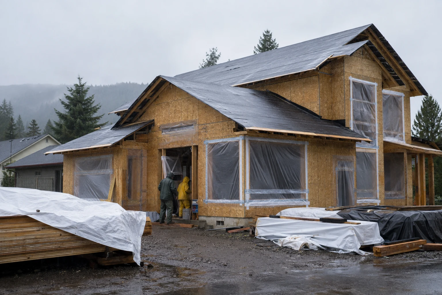
Building for Rainy Climates
Construction priorities for wind-driven rain, drainage, flashing, temporary protection, drying, and moisture verification in wet West Coast regions.
Read article
Coastal Construction: Corrosion, Wind, Rain, and Maintenance
Map salt, rain, wind and flood exposure before selecting materials; verify connections and maintenance access before concealing work.
Read article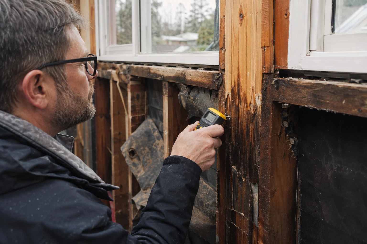
Moisture Control in Buildings: Design, Construction, and Maintenance
Stop the water source before rebuilding. Trace its path, measure affected materials and document project-specific acceptance before closure.
Read article