
Rainscreen Vent Strips: Top and Bottom Intake-Exhaust Sizing, Window Breaks and Bug Screens
Technical specification guide to rainscreen siding vent sizing, ventilated rainscreen intake and exhaust balance, rainscreen vent strip profiles, window breaks, and bug screens.
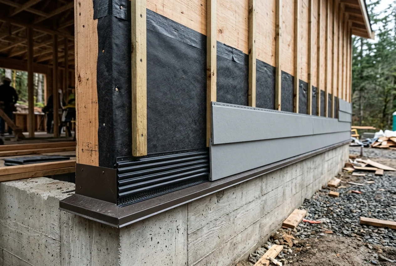
Selecting a rainscreen siding vent schedule begins with distinguishing a bottom-drained wall from a fully ventilated rainscreen assembly and matching each rainscreen vent strip to the furring depth, window flashing breaks, and insect or ember mesh requirements. For whole-wall assembly selection and membrane comparisons, see our Rainscreen Wall Systems Guide and browse the Building Materials hub.
Benjamin Obdyke states that while a basic rainscreen has a bottom opening for water exit, a ventilated rainscreen adds a top opening to create convective airflow (cold/dense air moving downward while hot/moist air pushes upward) and requires balanced top and bottom air openings.
Metal Architecture (Mark Robins) notes the two AAMA rainscreen classifications—drained, back-ventilated (AAMA 509-09) and pressure-equalized/pressure-moderated (AAMA 508-07)—and reports that designers calculate and specify the venting space thickness and venting air exchange (the vent strip perforation rate).
For a pressure-equalized rain screen (PER) wall system, smaller wall compartments require solid or non-cross-breathing furring strips (pressure-treated lumber or Sturdi-Strips), whereas drainage mat products and breathable or flow-through furring strips are not recommended.
Drained vs. Ventilated Rainscreen Airflow and Cavity Depth Thresholds
Evaluating rainscreen venting performance requires comparing documented wind-driven rain loads, code minimum capillary breaks, and convective drying cavity depths. For open-reveal facade boards where joints remain unsealed, see our Open-Joint Rainscreen Review.
The Construction Specifier (Keith Lolley, CSI) reports that Section 9.27.2.2 of the 2010 National Building Code of Canada (NBC) requires a drained and vented air space not less than 10 mm deep (3/8”) over the full height of the wall, notes ASTM E2925-14, and states an 80-km/h (50-mph) wind exerts 41.3 kPa (6 psi).
Metal Architecture (Peter Barrett) cites Dr. John Straube that 10 to 20 percent of wind-driven rain ends up behind the cladding, and reports that panels with both bottom and top vents dried faster than panels with only bottom vents, while a 19-mm (0.75-in.) cavity dried faster than a 10-mm (0.375-in.) cavity.
Metal Architecture cites a 2012 Lund University ventilated rainscreen study finding that a small cavity depth (less than 10 mm) prolongs ventilation drying, a 19 mm air cavity depth provides higher airflow and drying rates than a 10-mm cavity, and depths greater than 19 mm do not significantly influence drying rates.
BC Building and Safety Policy Branch Information Bulletin No. B08-02 (2006 BC Building Code) states that Article 9.27.5.3. requires wood furring used for structural cladding attachment to be at least 19 mm (3/4”) thick, whereas a capillary break spacer only needs to be 10 mm thick.
Under BC Building Code Appendix note A-9.27.2.2., proprietary capillary break products must allow drainage, create a 10 mm gap, and be not less than 80% open in cross section, while top venting and top/bottom bug screens are considered good practice rather than a Code requirement.
Fairview Architectural summarizes rainscreen cavity depth thresholds as 10 mm (3/8 in.) minimum lower bound for gravity drainage, 19 mm (3/4 in.) practical minimum for combined drainage and drying, 25 mm (1 in.) for Climate Zones 5–8 and impermeable cladding, and >38 mm (1.5 in.) where wind-washing risk may require baffling.
Dörken DELTA-DRY high-density polyethylene ventilated rainscreen membrane has an approx. 2/5” (10.5 mm) dimple height (ASTM D1777-96), 93 kPa (1,946 psf) compressive strength at 8% strain (ASTM D6364-06), and approx. 95% drainage efficiency (ASTM 2273).
Dörken DELTA-DRY provides a vapor permeance of 0.14 perms (ASTM E96, Method A) and has a contact surface of rainscreen to WRB of less than 20% (greater than 80% open).
Under ASTM E2954-14, DELTA-DRY achieved 1.18 L/s @ 10Pa ventilation/airflow and 1.94% drainage when tested with no DELTA-BUG SCREEN, and 1.41 L/s @ 10Pa ventilation/airflow and 0.65% drainage when tested with DELTA-BUG SCREEN.
Top and Bottom Intake-Exhaust Sizing and Net Free Vent Area (NFVA)
Sizing a rainscreen siding vent at the base and head of a wall compartment depends on published Net Free Vent Area (NFVA) ratings, intake-to-exhaust balance rules, and linear footage takeoff across wall runs and openings. For vertical batten layout and fastener penetration checks, see our Furring Strips for Rainscreen Siding Guide.
Fairview Architectural notes that in Division 07 42 43 (Faced Metal Panel Assemblies), a common reference for inlet and outlet vent sizing is 1 square inch of net free area per linear foot of wall width at both the base and head of each cavity compartment.
Benjamin Obdyke defines Net Free Area (NFA) as the open area for air passage and notes that under 2015 IRC Section R806 (1/150 minimum, or 1/300 with a vapor barrier or 3-foot height difference), exhaust ventilation must never exceed intake ventilation.
Screen Technology Group (WovenWire.com) states that net free ventilation area must account for louvers and the percent of open area allowed by the insect/pest screen, warning that many manufacturers exaggerate net free vent area by failing to deduct louver and insect screen airflow restrictions.
The Cor-A-Vent SV-3 Siding Vent has a 7/16” x 3” x 4’ cross section and provides 5 sq. in. of Net Free Vent Area (NFVA) per lineal foot.
The Cor-A-Vent SV-3 Rainscreen Siding Vent (7/16” thick by 3” high) achieves a 92% drainage efficiency per ASTM E 2273.
The SV-3 Siding Vent comes in 4-foot long sections, pairs with Sturdi-Strips or other 3/8” to 1/2” thick furring, and is packaged at 24 pieces per carton (96 lineal feet).
The Cor-A-Vent SV-5 Siding Vent has a 3/4” x 3” x 4’ cross section and provides 8.5 sq. in. of Net Free Vent Area (NFVA) per lineal foot.
The Cor-A-Vent SV-5 Rainscreen Siding Vent (3/4” thick by 3” high) achieves a 92% drainage efficiency per ASTM E 2273 and is packaged at 15 pieces per carton (60 lineal feet).
Where exterior rigid foam insulation is installed, Cor-A-Vent recommends 3/4” thick treated wood furring strips over the foam screwed into wall studs, with the SV-5 Siding Vent installed at the top and bottom.
Cor-A-Vent Sturdi-Strip furring strips measure 3/8” thick by 11/2” wide in 4-foot sections (112 pieces per carton, 448 lineal feet) and pair with SV-3 or doubled up to match SV-5.
Cor-A-Vent SV-3 runs linearly along the top and bottom of the wall as well as above and below windows or doors; linear footage is calculated by multiplying total wall length by 2 plus above and below wall penetrations.
For stud spacing on 16-inch centers, 1 linear foot of Sturdi-Strip is needed per square foot of wall (500 lineal feet for 500 square feet), while 2-foot on-center spacing requires 80% (0.8, or 400 lineal feet).
| Sizing Parameter or Product | Documented Net Free Vent Area and Takeoff Specification |
|---|---|
| Commercial metal panel baseline | Fairview Architectural notes that in Division 07 42 43 (Faced Metal Panel Assemblies), a common reference for inlet and outlet vent sizing is 1 square inch of net free area per linear foot of wall width at both the base and head of each cavity compartment. |
| Intake-to-exhaust balance rule | Benjamin Obdyke defines Net Free Area (NFA) as the open area for air passage and notes that under 2015 IRC Section R806 (1/150 minimum, or 1/300 with a vapor barrier or 3-foot height difference), exhaust ventilation must never exceed intake ventilation. |
| Thin-furring fluted polypropylene vent | The Cor-A-Vent SV-3 Siding Vent has a 7/16" x 3" x 4' cross section and provides 5 sq. in. of Net Free Vent Area (NFVA) per lineal foot. |
| Thick-furring fluted polypropylene vent | The Cor-A-Vent SV-5 Siding Vent has a 3/4" x 3" x 4' cross section and provides 8.5 sq. in. of Net Free Vent Area (NFVA) per lineal foot. |
| Horizontal vent strip takeoff | Cor-A-Vent SV-3 runs linearly along the top and bottom of the wall as well as above and below windows or doors; linear footage is calculated by multiplying total wall length by 2 plus above and below wall penetrations. |
Rainscreen Vent Strip Profiles: Polypropylene, Rigid PVC, and Extruded Aluminum
Comparing rainscreen vent strip and starter profiles requires checking material composition, perforation geometry, non-venting starter boundaries, and dark-paint thermal limits.
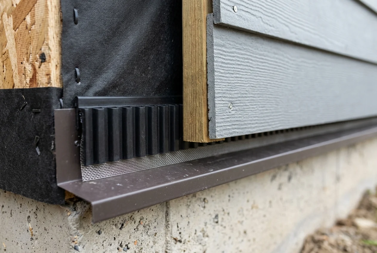
Cor-A-Vent Sturdi-Batten is a three-ply heat-resistant polypropylene vented batten strip measuring 7/16” thick by 1-1/2” wide in 4-foot sections (48 pieces per carton, 192 lineal feet) that pairs with the SV-3 siding vent.
Cor-A-Vent Sturdi-Starter is a 4-foot long x 1 1/4” wide x5/16” thick (8 mm) profile extruded polypropylene starter strip used behind the first course of fiber cement siding and above windows and doors.
On the Cor-A-Vent SV-3 detail sheet, Sturdi-Starter (11/4’’ by 8MM, 4’ length) is an optional starter strip accessory and is explicitly labeled non-venting.
Independent testing agency PRI Construction Material Technologies tested Cor-A-Vent SV-3, SV-5, and Sturdi-Strip to Florida Building Code (2010) Section 2606.4 using ASTM D 635-03, ASTM D 635-06, ASTM D 1929-96, and ASTM E 136 -12 at 750°C.
PRI Construction Material Technologies tested compressive strength under ASTM 1621-10 and tensile strength under ASTM D 638 before and after 2,000 hours of ASTM G 154 UV weathering (12 hour cycles: 8 hours UV at 158°F and 4 hours condensation at 104°F).
PRI Construction Material Technologies tested two 4’x 8’ wall specimens (2 x 4 framing, 1-1/2” roofing nail, 7/16” OSB, ICC-ES AC 38 WRB, and SV-3 with Enhanced Insect Screen) under modified ASTM E 2273-03(2011) and ICC-ES AC356.
The Fry Reglet VT2 / VT3 Rain Screen Vent Strip is a black extruded PVC member (2 5/16” overall height, unlabeled 3/8” profile dimension, available in 10’ lengths) that captures the bottom edges of 3/8” and 3/4” furring strips to allow moisture mitigation and free airflow.
Fry Reglet VT2 (Part Number FCP-VST375) has a nominal 3/8” reveal depth and VT3 (Part Number FCP-VST75) has a nominal 3/4” reveal depth for 5/16” Fiber Cement Panel rain screen assemblies.
Tamlyn Item ID VST is a paintable white extruded rigid PVC rainscreen top vent in 8’ lengths (listed at 3/8” rainscreen size for 3/8” to 3/4” furring thicknesses), perforated with 1/8” holes, and must be used together as a system with CR and VSZ.
Tamlyn VSZ is a paintable white extruded rigid PVC starter course perforated with 1/8” holes for moisture weeping and pest resistance, offered in VSZ38 (2” by 3/8” by 3/8”), VSZ12 (1/2” rainscreen size), and VSZ34 (3/4” rainscreen size).
Tamlyn warns to use only light or pastel paint colors or Sherwin-Williams Vinyl Safe Paint on Tamlyn rigid PVC rainscreen vents; dark color paint will cause deformation and voids the warranty.
Tamlyn XtremeTrim fiber cement siding accessories (Section 07 46 00) include Starter Strip XS and Window Flashing XWF made of 6063 T5 extruded aluminum.
Tamlyn XtremeTrim anodized finish is Architectural 200R1 light etch (AA-M32c10A21) in clear color, with anodic coating thickness tested in accord with ASTM B244-97 and sealed to pass ASTM B136-84.
Dörken DELTA-DRY has a temperature range of -22°F to +176°F (-30°C to +80°C), a service life expectancy of > 20 years (at pH between 4 and 9), and must not be exposed to UV light for more than 30 days.
Dörken DELTA-DRY holds code and evaluation approvals under ICC-ES ESR-2987, AC188, and AC356.
| Profile Family | Documented Dimensions, Material, and Application |
|---|---|
| Three-ply polypropylene vertical batten | Cor-A-Vent Sturdi-Batten is a three-ply heat-resistant polypropylene vented batten strip measuring 7/16" thick by 1-1/2" wide in 4-foot sections (48 pieces per carton, 192 lineal feet) that pairs with the SV-3 siding vent. |
| Non-venting polypropylene starter strip | On the Cor-A-Vent SV-3 detail sheet, Sturdi-Starter (11/4'' by 8MM, 4' length) is an optional starter strip accessory and is explicitly labeled non-venting. |
| Black extruded PVC panel vent strip | Fry Reglet VT2 (Part Number FCP-VST375) has a nominal 3/8" reveal depth and VT3 (Part Number FCP-VST75) has a nominal 3/4" reveal depth for 5/16" Fiber Cement Panel rain screen assemblies. |
| Perforated white rigid PVC top vent | Tamlyn Item ID VST is a paintable white extruded rigid PVC rainscreen top vent in 8' lengths (listed at 3/8" rainscreen size for 3/8" to 3/4" furring thicknesses), perforated with 1/8" holes, and must be used together as a system with CR and VSZ. |
| Perforated white rigid PVC starter course | Tamlyn VSZ is a paintable white extruded rigid PVC starter course perforated with 1/8" holes for moisture weeping and pest resistance, offered in VSZ38 (2" by 3/8" by 3/8"), VSZ12 (1/2" rainscreen size), and VSZ34 (3/4" rainscreen size). |
| Extruded aluminum starter and flashing | Tamlyn XtremeTrim fiber cement siding accessories (Section 07 46 00) include Starter Strip XS and Window Flashing XWF made of 6063 T5 extruded aluminum. |
Base-of-Wall, Window Sill and Head Breaks, Multi-Story Compartments, and Eave Terminations
Continuous ventilated rainscreen airflow requires planned clearances at grade, flashing breaks above and below windows, intermediate floor-line vents on taller facades, and code-compliant top-of-wall blocking at eaves and soffits. For pan flashing back-dam and jamb shingle-lap checks, see our Window Flashing and Sill-Pan Guide.
PNNL / U.S. DOE Building America guidance states that the drainage/ventilation gap should be 1 or more inches behind brick or stone veneer, 3/4 inch behind stucco, and 1/16 inch behind lap siding, with base flashing lapped at least 8 inches and kept at least 8 inches above grade.
PNNL / U.S. DOE Building America recommends sloping the ground away from the building at a 5% slope (a 5-inch drop per 100 feet, or about 5/8-inch per foot).
PNNL / U.S. DOE Building America states that in a wood or fiber-cement rain screen assembly, vertical wood or plastic furring strips at least 3/8 inches thick are spaced every 16-24 inches and nailed every 12-16 inches with 5d galvanized nails, with nylon screening pinned by the starter strip.
In DELTA-DRY installations, window and door openings must be flashed into the WRB per ASTM E-2112-07 or AAMA 2400-02, and at the top of all windows and doors DELTA-BUG SCREEN is installed at the bottom edge of flashing directly beneath DELTA-DRY.
Under BC Building Code Clause 9.27.3.8.(4)(c), window head flashing end dams can be 25 mm high or calculated from local driving rain wind pressure (16 mm high at 160 Pa in the Fraser Valley and Greater Vancouver; 50 mm calculated at 500 Pa in Sandspit, with the option of 25 mm).
In Cor-A-Vent’s vinyl and wood window details using SV-3 (7/16’‘) or SV-5 (3/4’‘), the window head detail provides a drainage/airflow opening of 1/16’’ approx. above the rigid flashing and the sill detail provides a vent opening of 1/16’’ approx. below the sill.
In Cor-A-Vent’s window jamb and sill details, furring strips are 1/2’’ x 2’’ when using SV-3 and 3/4’’ x 2’’ when using SV-5.
Under Dörken DELTA-DRY installation rules, ventilation is required at the bottom of windows and doors wider than 6 ft (1.8 m), whereas for windows and doors less than 6’ (1.8 m) wide, no ventilation gap is required at the bottom.
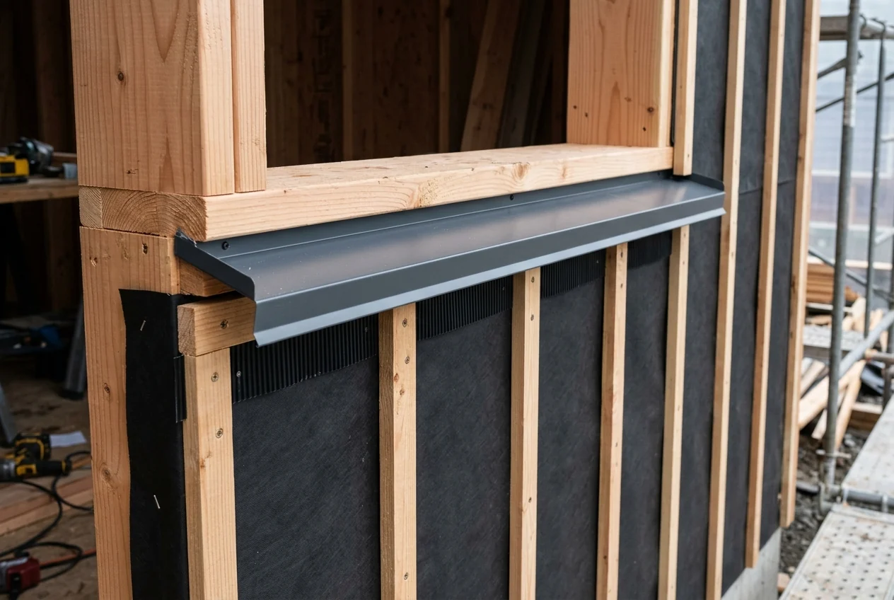
For DELTA-DRY installations on buildings over two stories high, a horizontal ventilation detail must be installed every two stories, and in Climate Zone 4C (Marine), a horizontal ventilation detail must be installed every story.
In the Cor-A-Vent SV-3 top-of-wall detail, a 1/4’’ opening is shown at the top and a 1/8’’ opening below, and siding must be nailed through SV-3 and through Sturdi-Strips into the structure behind.
At the top of walls, DELTA-DRY installation requires wood blocking extending beyond the top edge of cladding by at least 3/8” (10 mm) with DELTA-BUG SCREEN fastened against the bottom of the blocking and a molding piece overlapping the cladding by at least 2” (5 cm).
For DELTA-DRY top-of-wall molding protecting the 3/8” (10 mm) air gap, in areas with wind speeds greater than 60 mph (96 km/h), the leg of the vertical molding piece may need to be longer than 2” (5 cm).
Under Sentence 9.27.2.2.(3) of the BC Building Code, connecting the 10 mm capillary break air space with projecting construction (such as roof and floor assemblies) is specifically prohibited, and the Code does not permit venting the capillary break into a vented attic.
Under ORSC Section R327.3.3.1, exterior wall coverings must extend from the top of the foundation to the roof and terminate at 2-inch (50.8 mm) nominal solid wood blocking between rafters at all roof overhangs, or in the case of enclosed eaves or soffits, terminate at the underside of the enclosure.
Under ORSC Section R327.3.2.1, ventilation openings shall not be installed on the underside of eaves, soffits, or cornices unless approved as manufactured to resist flame and burning embers or complying with Section R327.3.2 and located 12 feet (3658 mm) or greater above grade.
Bug Screen Mesh Geometry, Coastal Salt-Spray Alloys, and WUI Wildfire Compliance
Selecting woven metal screening for rainscreen venting inlets and outlets requires balancing open area percentage against insect exclusion, marine salt-spray corrosion resistance, and Wildland-Urban Interface (WUI) ember size limits. For attic, gable, and crawlspace ember-vent assemblies, see our Wildfire-Resistant Vent Retrofits Guide and our Coastal Construction Guide.
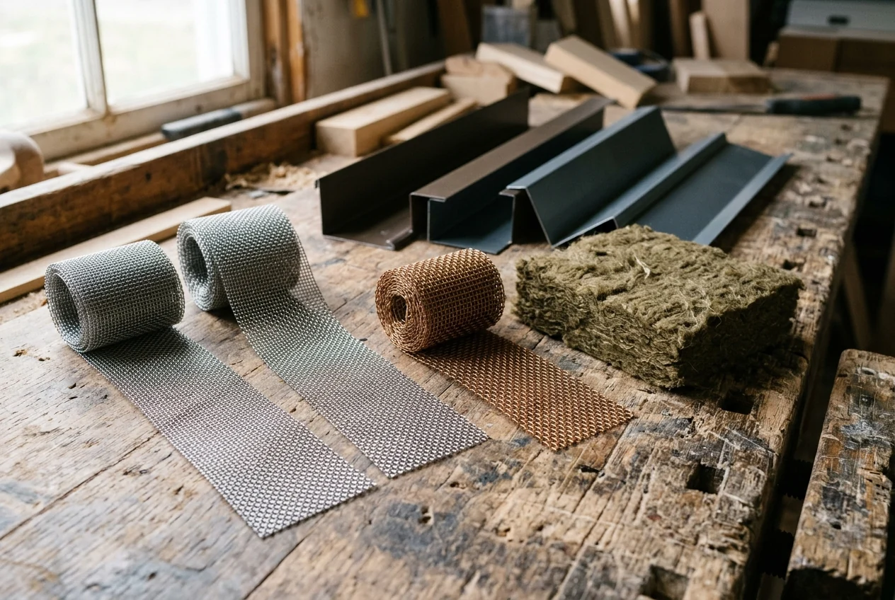
Under Oregon Residential Specialty Code (ORSC) Section R327.3.2, ventilation openings (sized to Sections R806 and R408) must be covered with noncombustible corrosion-resistant metal wire mesh measuring a minimum of 1/16-inch (1.6 mm) and a maximum of 1/8-inch (3.2 mm) in any dimension, or ember/flame-resistant vents.
IBHS wind-driven ember research finds that 1/4-in. mesh screening (6 mm) should not be used to cover any vent, that finer mesh sizes of 1/8 in. (3 mm) or 1/16 in. (1.5 mm) are preferred, and that the finer 1/16-in. mesh screen requires more cleaning-related maintenance to remove accumulated surface debris.
Screen Technology Group specifies Standard Duty Stainless Steel (T-304 and T-316) vent screens with 0.009” wire diameter in 14 x 14 mesh (0.062” / 1.575 M.M. opening, 76.4% open area) and 16 x 16 mesh (0.053” / 1.358 M.M. opening, 73.3% open area).
Screen Technology Group specifies Standard Duty Stainless Steel (T-304 and T-316) vent screens with 0.009” wire diameter in 18 x 18 mesh (0.046” / 1.168 M.M. opening, 70.2% open area), 18 x 14 mesh (0.046” x 0.062” opening, 73.2% open area), and 20 x 20 mesh (0.041” / 1.041 M.M. opening, 67.2% open area).
Screen Technology Group specifies Commercial and Industrial Grade Stainless Steel (T-304 and T-316) vent screens in 4 x 4 mesh (0.215” / 5.461 M.M. opening, 0.035” wire, 74% open area) and 6 x 6 mesh (0.138” / 3.505 M.M. opening, 0.028” wire, 69.2% open area).
Screen Technology Group specifies three Commercial and Industrial Grade Stainless Steel (T-304 and T-316) 8 x 8 meshes: 0.108” (2.743 M.M.) opening with 0.017” wire (74.6% open area), 0.105” (2.667 M.M.) opening with 0.020” wire (70.6% open area), and 0.100” (2.540 M.M.) opening with 0.025” wire (64% open area).
For coastal applications subject to direct salt sprays or ocean air, Screen Technology Group recommends copper, brass, bronze, or Monel 400 (nickel-copper alloy), listing Commercially Pure Copper soffit vent screens at 4 openings per inch (0.203” / 5.516 M.M., 0.047” wire, 65.9% open area) and 8 openings per inch (0.097” / 2.464 M.M., 0.028” wire, 60.2% open area).
Screen Technology Group states that hot-dip galvanized vent screens usually last a minimum of 10 years up to a maximum of 20 years, and their rough wire surface causes dirt and grime to adhere and build up until considerable open area is lost.
Screen Technology Group specifies Galvanized Soffit and Ground Vent Screens in 4 Mesh (0.224” / 5.69 M.M. opening, 23 gauge, 0.0258” wire, 80.4% open area) and 8 Mesh (0.108” / 2.74 M.M. opening, 27 gauge, 0.0173” wire, 74.2% open area), noting both exclude rodents, birds, and squirrels but not insects.
| Mesh Alloy and Grade Category | Documented Mesh Count, Aperture, Wire Diameter, and Open Area |
|---|---|
| Standard duty stainless steel fine insect mesh | Screen Technology Group specifies Standard Duty Stainless Steel (T-304 and T-316) vent screens with 0.009" wire diameter in 14 x 14 mesh (0.062" / 1.575 M.M. opening, 76.4% open area) and 16 x 16 mesh (0.053" / 1.358 M.M. opening, 73.3% open area). |
| Standard duty stainless steel ultra-fine insect mesh | Screen Technology Group specifies Standard Duty Stainless Steel (T-304 and T-316) vent screens with 0.009" wire diameter in 18 x 18 mesh (0.046" / 1.168 M.M. opening, 70.2% open area), 18 x 14 mesh (0.046" x 0.062" opening, 73.2% open area), and 20 x 20 mesh (0.041" / 1.041 M.M. opening, 67.2% open area). |
| Commercial grade stainless steel coarse mesh | Screen Technology Group specifies Commercial and Industrial Grade Stainless Steel (T-304 and T-316) vent screens in 4 x 4 mesh (0.215" / 5.461 M.M. opening, 0.035" wire, 74% open area) and 6 x 6 mesh (0.138" / 3.505 M.M. opening, 0.028" wire, 69.2% open area). |
| Commercial grade stainless steel ember-range mesh | Screen Technology Group specifies three Commercial and Industrial Grade Stainless Steel (T-304 and T-316) 8 x 8 meshes: 0.108" (2.743 M.M.) opening with 0.017" wire (74.6% open area), 0.105" (2.667 M.M.) opening with 0.020" wire (70.6% open area), and 0.100" (2.540 M.M.) opening with 0.025" wire (64% open area). |
| Coastal salt-spray copper and nickel-copper alloy | For coastal applications subject to direct salt sprays or ocean air, Screen Technology Group recommends copper, brass, bronze, or Monel 400 (nickel-copper alloy), listing Commercially Pure Copper soffit vent screens at 4 openings per inch (0.203" / 5.516 M.M., 0.047" wire, 65.9% open area) and 8 openings per inch (0.097" / 2.464 M.M., 0.028" wire, 60.2% open area). |
| Hot-dip galvanized rodent and bird mesh | Screen Technology Group specifies Galvanized Soffit and Ground Vent Screens in 4 Mesh (0.224" / 5.69 M.M. opening, 23 gauge, 0.0258" wire, 80.4% open area) and 8 Mesh (0.108" / 2.74 M.M. opening, 27 gauge, 0.0173" wire, 74.2% open area), noting both exclude rodents, birds, and squirrels but not insects. |
Common questions
How is Net Free Area balanced between rainscreen intake and exhaust openings?
Benjamin Obdyke defines Net Free Area (NFA) as the open area for air passage and notes that under 2015 IRC Section R806 (1/150 minimum, or 1/300 with a vapor barrier or 3-foot height difference), exhaust ventilation must never exceed intake ventilation.
Can a rainscreen capillary break cavity vent directly into an attic or soffit?
Under Sentence 9.27.2.2.(3) of the BC Building Code, connecting the 10 mm capillary break air space with projecting construction (such as roof and floor assemblies) is specifically prohibited, and the Code does not permit venting the capillary break into a vented attic.
When is bottom window sill ventilation required in a DELTA-DRY rainscreen wall?
Under Dörken DELTA-DRY installation rules, ventilation is required at the bottom of windows and doors wider than 6 ft (1.8 m), whereas for windows and doors less than 6’ (1.8 m) wide, no ventilation gap is required at the bottom.
What wire mesh opening size is required for wildfire ember resistance under ORSC R327.3.2?
Under Oregon Residential Specialty Code (ORSC) Section R327.3.2, ventilation openings (sized to Sections R806 and R408) must be covered with noncombustible corrosion-resistant metal wire mesh measuring a minimum of 1/16-inch (1.6 mm) and a maximum of 1/8-inch (3.2 mm) in any dimension, or ember/flame-resistant vents.
Return to our Building Materials hub to coordinate cladding, flashing, and enclosure specifications across your project.
Sources
- Cor-A-Vent — Ventilation Products NFVA & Dimensions Chart
- Cor-A-Vent — SV-3 Siding Vent Product & Technical Specification
- Cor-A-Vent — SV-3 Siding Vent Product Data & Installation Sheet (PDF)
- Cor-A-Vent — SV-5 Rainscreen Siding Vent Product & Technical Specification
- Cor-A-Vent — Rainscreen Siding Ventilation Guide (RainscreenBrochure.pdf)
- Fry Reglet — Fiber Cement Profiles VT2 & VT3 Rain Screen Vent Strip Submittal Sheet (PDF)
- Tamlyn — Water Management Catalog: Rainscreen Vent Strip / Top Vent (VST.pdf)
- Tamlyn — Xtreme Trim Rainscreen Top Vent Product Specification
- Tamlyn — XtremeTrim Extruded Aluminum Trim Specification (Section 07 46 00)
- Dörken Systems Inc. — DELTA-DRY Technical Data Sheet (including DELTA-BUG SCREEN)
- Dörken Systems Inc. — DELTA-DRY Installation Instructions (Top/Bottom Ventilation & DELTA-BUG SCREEN)
- Benjamin Obdyke — What Is Net Free Area (NFA)?
- Benjamin Obdyke — When and How to Implement a Ventilated Rainscreen
- BC Building and Safety Policy Branch — Information Bulletin B08-02: Capillary Break (Rainscreen) Cladding Systems
- PNNL / U.S. DOE Building America Solution Center — Flashing at Bottom of Exterior Walls
- The Construction Specifier (Keith Lolley, CSI) — Draining the Rain: Advancements in engineered rainscreen walls
- Metal Architecture — Evolution of Rainscreens
- Metal Architecture — Metal Rainscreen Primer
- Metal Architecture — Urban Wildfire Resilience
- Screen Technology Group, Inc. (WovenWire.com) — Insect and Pest Screens for Roof Soffit Vent and Foundation Vents
- Oregon Building Codes Division — Oregon Residential Specialty Code (ORSC) Section R327 Wildfire Hazard Mitigation
- Insurance Institute for Business & Home Safety (IBHS) — Vulnerability of Vents to Wind-Blown Embers Executive Summary (PDF)
- Fairview Architectural North America — How Rainscreen Cavity Depth Affects Drainage Performance
- Hammer & Hand — Best Practices Manual: 4.3 Rain Screens: Bottom of Window
Related articles
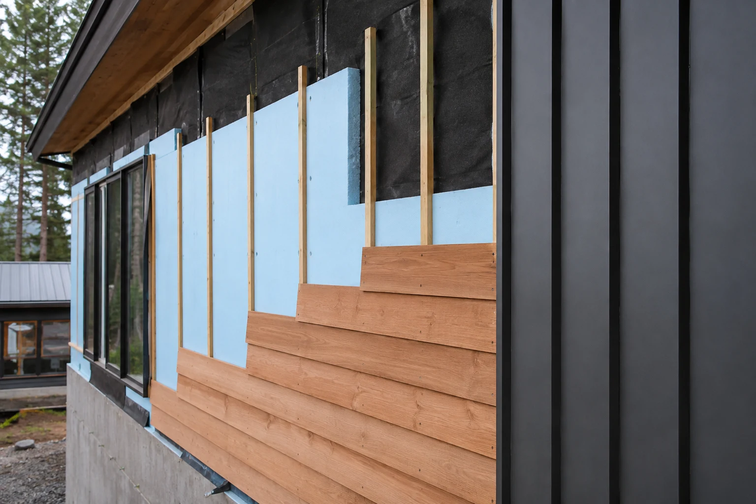
Rainscreen Wall Systems: Design and Construction Guide
Choose drained, ventilated or engineered pressure-controlled walls first; keep the selected system's drainage and ventilation outlets clear.
Read article
Furring Strips for Vinyl Siding: Rainscreen Gap or Nail Base?
Furring can level a vinyl siding wall, hold fasteners or create drainage space. Check the water path and fastening role before calling it a rainscreen.
Read article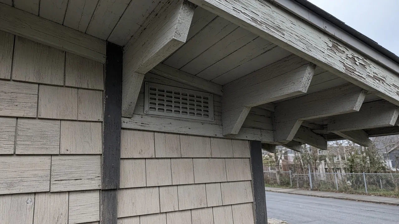
Wildfire-Resistant Vent Retrofits: Record Airflow, Listing and Fit
How to document vent locations, CSFM listing numbers, mesh aperture limits, and net free ventilation area (NFVA) before ordering wildfire-resistant retrofit vents.
Read article