
Earthquake Brace and Bolt Retrofit: Anchors vs. Sheathing
Foundation anchors and cripple-wall sheathing address different weaknesses. Compare their roles and learn what a grant checklist cannot establish.
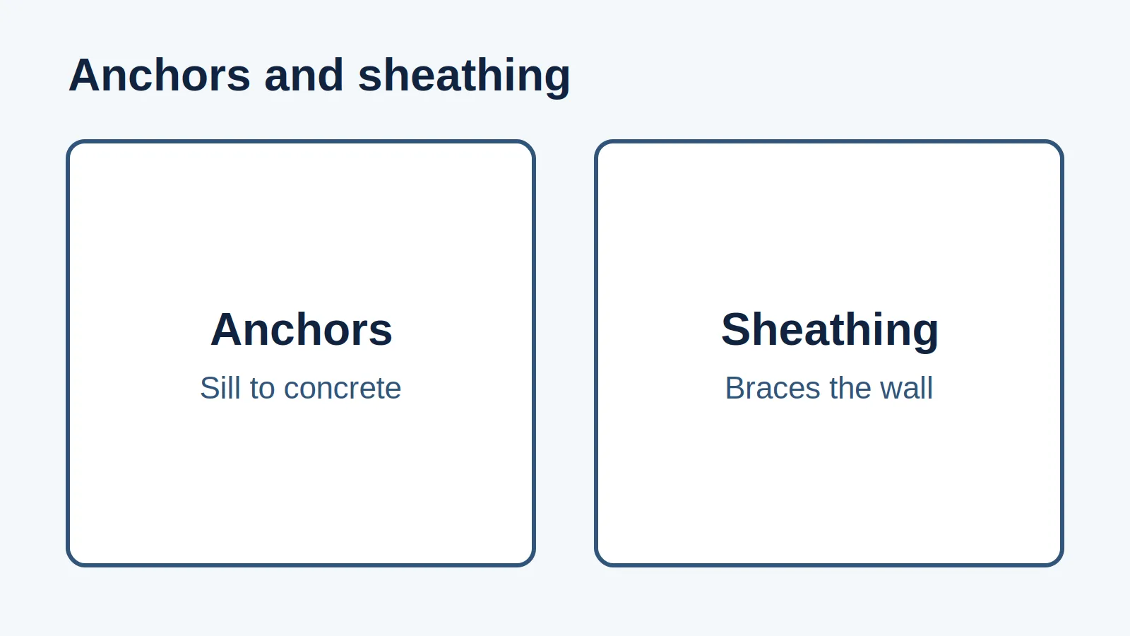
An earthquake brace and bolt retrofit connects a raised-foundation wood house to its foundation and strengthens vulnerable short walls below the floor. Anchors resist movement at the wood-to-concrete connection; structural sheathing braces the framed cripple wall. Each needs the connections around it to work. A grant checklist can track program requirements, but it cannot by itself establish that every structural weakness has been addressed.
What is being strengthened?
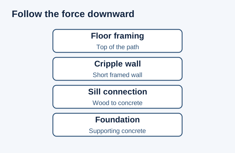
A cripple wall is the short framed wall between the foundation and the occupied floor above. Follow the force-transfer route downward: floor framing, connection to the cripple wall, braced wall, sill connection and concrete foundation. The condition of each link matters. A panel fastened to deteriorated framing or an anchor installed in unsuitable concrete leaves a problem at the connection.
FEMA P-1100 treats foundation anchorage, cripple-wall bracing and the connection to the floor immediately above as a related crawlspace vulnerability. Its October 2019 guide, hosted by CRMP, separates these components in Chapter 4. Use the broader seismic retrofit guide to distinguish this work from garage-story, hillside and masonry assessments.
What does each component prevent?
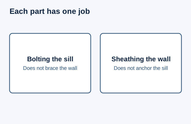
Bolting the sill to concrete does not make an unbraced framed wall resist sideways distortion. Sheathing the wall does not establish a connection to the foundation. The comparison is between functions within one retrofit, rather than competing products.
Swipe or scroll horizontally to view all columns →
| Component | Structural job | What to verify before concealment | Dominant Failure Mode & Prevention |
|---|---|---|---|
| Foundation anchor or approved foundation plate | Transfer force between the wood sill/frame and concrete foundation | Selected detail, foundation and wood condition, installation and required inspection records | Sliding at the base connection → provide the designed anchorage into suitable supporting materials |
| Structural-panel cripple-wall sheathing | Help the short framed wall resist lateral distortion | Panel locations, supporting framing, edges and fastening against the accepted drawing | Wall racking or collapse → install the specified bracing assembly, including its connections |
| Connection to floor framing above | Transfer forces between the occupied floor and the supporting wall or sill | The actual floor arrangement and matching connection detail | Discontinuity above the braced wall → complete the upper connection rather than stopping at the panel |
CRMP’s EBB retrofit explanation distinguishes brace-and-bolt houses from houses whose wood frame bears directly on the foundation. The latter may need a bolt-only scope. That distinction comes from the actual framing arrangement; a crawlspace photograph of one corner cannot establish the arrangement around the whole house.
When does the simplified assessment route stop applying?
Threshold rule: Under FEMA P-1100 Table 4.3-1, item 1, for Configuration A crawlspace dwellings, a tallest cripple wall over 4 feet triggers engineered assessment or retrofit of the sheathing, foundation anchorage and connection to the dwelling above. Measure the tallest condition, not the easiest wall to reach.
This is a threshold within that specific simplified assessment procedure. A shorter wall still has to satisfy the procedure’s other conditions. A taller wall is not automatically excluded from every retrofit method or grant program. Identify the applicable assessment route and locally accepted documents with the design professional and building department before choosing construction details.
Do not derive bolt diameters, spacing, panel fastening or foundation suitability from this screening rule. Different geometry, existing deterioration and altered floor layouts can change the required work.
What can a panel-area calculation tell you?
A simple takeoff can make a scope discussion more concrete. For a rectangular sheathed face:
Panel face area, A = sheathed length, L × sheathed height, H.
Example with assumed dimensions: A = 8 ft × 3 ft = 24 ft² for one face.
This is material area before cutting losses and openings. It is not a required bracing length, panel layout, fastener quantity or lateral strength. Two scopes with the same area can place panels differently or omit different connections. Compare each wall line against the accepted drawing before comparing material totals.
What does a grant checklist establish?
Separate program administration from technical acceptance. An eligibility answer, uploaded photograph or payment record establishes only what that document actually records. Keep the grant requirements alongside the permit and inspection records so the scope remains traceable.
FEMA P-1100 allows vulnerability-based work to address selected weaknesses. It also says that incomplete work within the selected vulnerability cannot be designated as conforming, and that phased work needs its load-path connections when the element is installed (§§1.4.1–1.4.2). A limited scope and an unfinished load path are different conditions.
Use this owner record to make the distinction visible:
- Scope: Identify each wall line, connection and existing condition included in the accepted work; list exclusions separately.
- Before-cover evidence: Match photographs and required inspection records to the anchor, panel and upper connection locations on the drawing.
- Changes: Retain the accepted revision when pipes, access limits or damaged materials require a different detail.
- Closeout: Keep the permit sign-off and program completion documents with the installed-scope record.
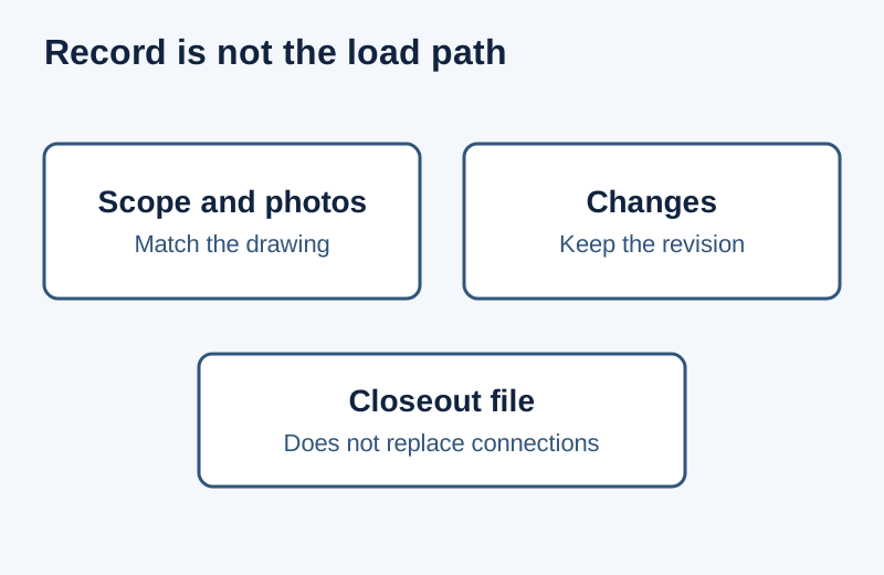
The conclusion is deliberately bounded: a completed grant checklist alone does not prove concealed workmanship, foundation adequacy or whole-building earthquake safety. FEMA describes damage reduction rather than prevention of all damage; its vulnerability-based methods also leave site hazards such as liquefaction and landslide outside their required assessment scope (§§1.2 and 1.9).
What work can disappear from a headline price?
Access preparation, investigation of existing concrete, repair of damaged framing, moisture correction and restoration after inspection can affect total project cost. An inexpensive hardware allowance says little about whether those tasks are included. Compare the completed scope, required access and inspection sequence rather than the number of visible bolts.
Where wet or decayed framing is found, coordinate repairs with the moisture-control guide before covering it. Keep future crawlspace access and required ventilation coordinated with bracing details. The climate and durability hub connects these structural and moisture decisions.
Sources reviewed October 19, 2026: FEMA P-1100, October 2019, Chapter 1, Table 4.3-1 and §§4.4.5–4.4.8; and CRMP’s live EBB retrofit explanation. The source review supports the component comparison and screening distinction; the project still needs its applicable design and inspection route.
Related articles
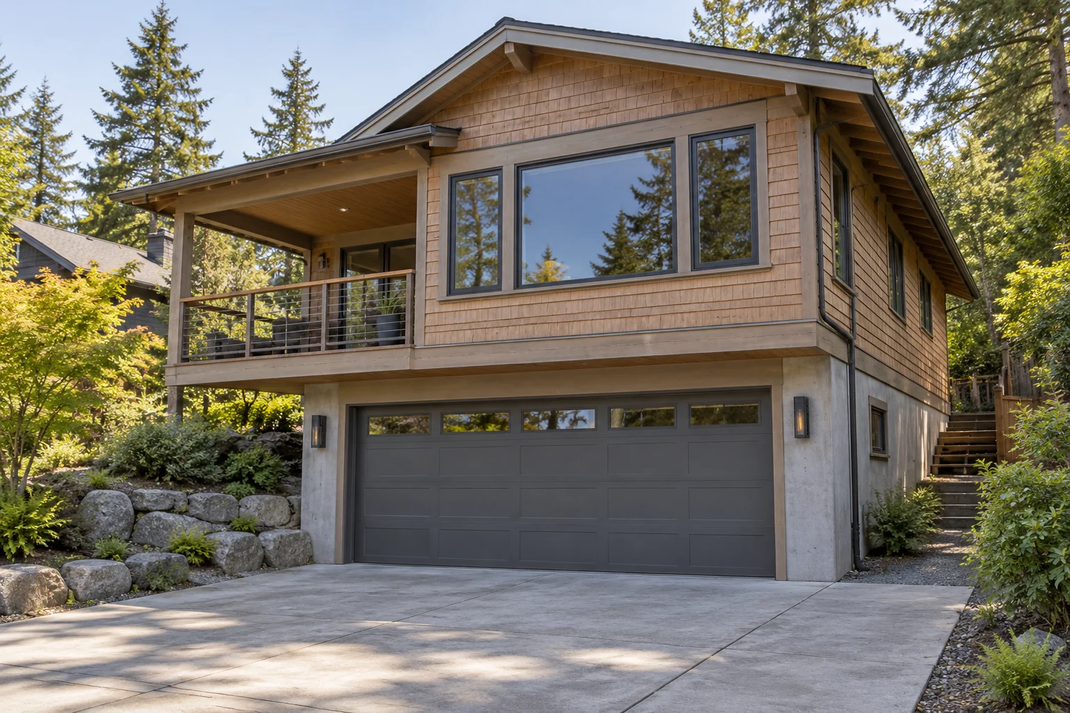
Soft-Story vs Cripple-Wall Retrofit: Ground-Floor Garage Openings vs Crawlspace Bracing
Compare soft story retrofit options at garage openings with crawlspace bracing, foundation connections, and a documented moment-frame example.
Read articleCoastal Construction Products: ASTM C920 Sealants, AAMA 711 Flashing, and Type 316 Fasteners
Selecting coastal construction products requires ASTM C920 Class 50 STPE or silicone sealants, AAMA 711 Level 3 flashings, and Type 316 stainless fasteners to prevent leaks and corrosion rework.
Read article
WUI Noncombustible Construction: Comparing Oregon R327 Against La Cañada Flintridge VHFHSZ Notes
Oregon R327 and the La Cañada Flintridge wildfire notes differ on accessory size, roof class, eave height, vents, and glass.
Read article