
Cladding Attachments and Thermal Bridging: Evidence to Check
Compare girt, clip-and-rail and long-screw cladding supports by the structural, thermal and interface evidence each needs before trusting nominal R-values.
Judging a cladding attachment by the insulation board’s nominal R-value can hide the metal that crosses it, a mistake that is costly to correct once the cladding is on. Discrete clips with rails kept outside the insulation usually put less metal through the insulation than continuous girts, and for mid- and high-rise walls with greater rain exposure they are the approach RDH typically recommends. Long screws through rigid insulation into exterior strapping cross it only at each screw, but they are described for light- to medium-weight cladding and suit low-rise wood-frame buildings with lower rain exposure best. Which option fits a given commercial wall still depends on cladding weight, wind and seismic loads, the back-up wall and the real clip layout at windows and floor lines.
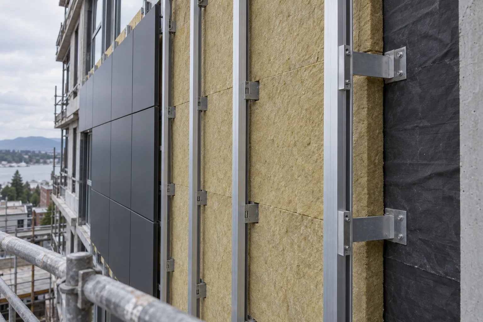
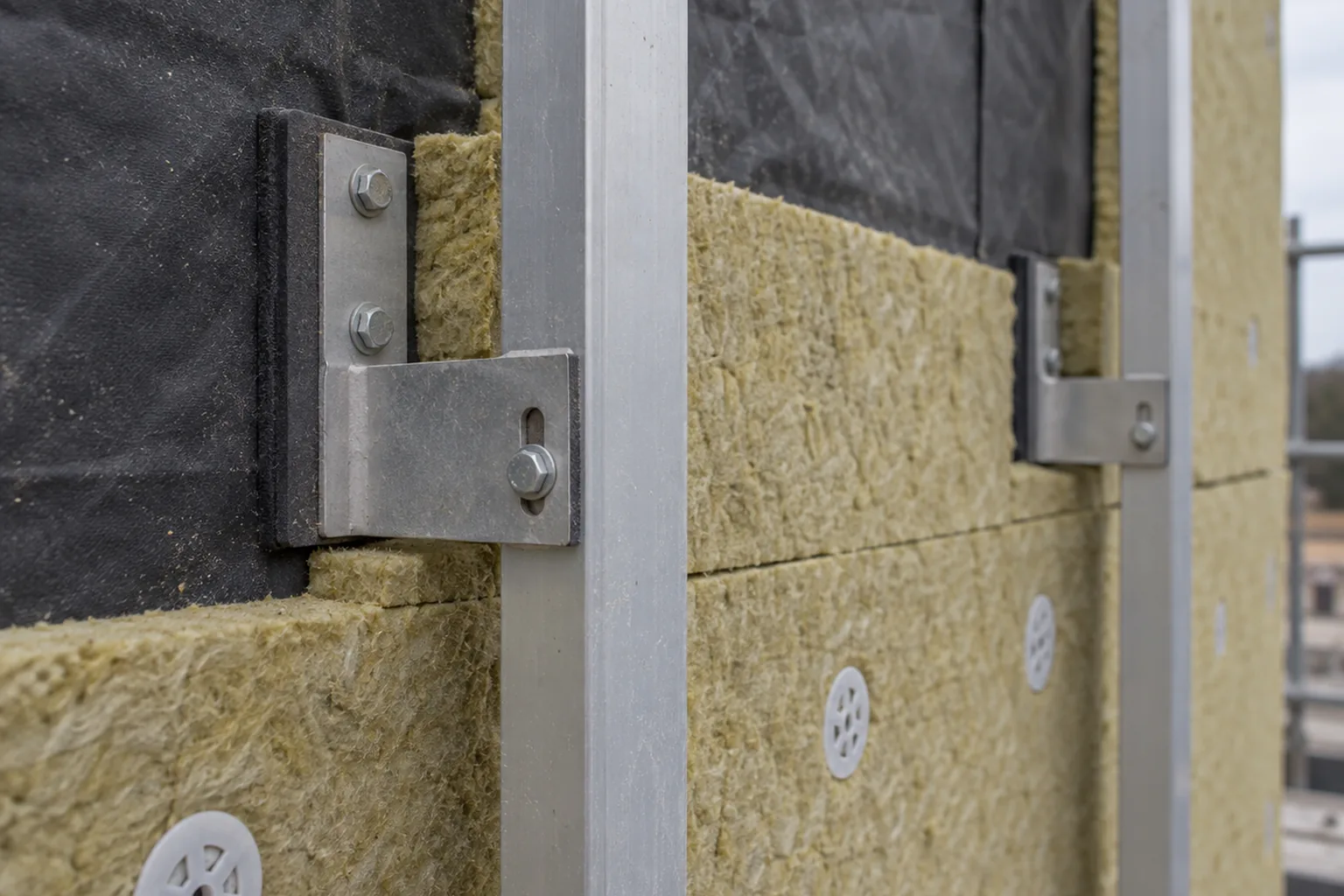
This technical comparison summarizes published building-envelope guidance, primarily RDH Building Science’s April 2018 (V4) bulletin on cladding attachment for exterior-insulated commercial walls. It sits under the Building Materials hub and goes deeper than the attachment section of the rainscreen wall systems guide. The cover illustration depicts exterior continuous insulation with clip-and-rail subframing prior to panel installation.
Which rainscreen attachment methods reduce thermal bridging on continuous insulation for office buildings? Compare the metal path through the insulation first: continuous girts bridge it along their whole length, clip-and-rail systems bridge it only at the clips when the rail stays outboard, and long-screw systems bridge it only at the screws but are described for light- to medium-weight cladding on low-rise wood-frame buildings with lower rain exposure, because their membrane penetrations cannot be sealed after installation. For mid- and high-rise office walls with greater exposure, RDH typically recommends clip-and-rail systems whose clip fasteners are sealed before the insulation goes on. Then confirm that the structural design for dead, wind and seismic load, the actual number of clips at openings and floor lines, and a thermal model matched to your back-up wall and insulation thickness all support the same choice. No method wins without that evidence.
Swipe or scroll horizontally to view all columns →
| Input or item | Where it comes from | Why it matters |
|---|---|---|
| Cladding type, weight and orientation | Architectural drawings and cladding manufacturer documents | Heavier cladding or stronger wind usually means closer supports and more metal through the insulation |
| Back-up wall and anchorage target | Structural drawings; existing-condition survey on retrofits | Decides whether clips or screws can reach studs, sheathing, concrete or slab edge |
| Insulation type and thickness | Envelope drawings and energy design | Changes eccentric load on the supports and limits which thermal values are comparable |
| Attachment system and materials | Proposed system documents and the attachment designer’s submittal | Clip, rail and fastener materials and geometry set the thermal path |
| Structural basis | Engineer’s calculations or the manufacturer’s load tables, with their stated conditions | Supports must carry dead, wind and seismic load and limit deflection |
| Thermal basis | Three-dimensional thermal model or clip χ-value for a matching assembly | Nominal insulation values ignore the attachment |
| Detail density | Elevations and details at windows, joints, flashings and floor lines | Real walls need more supports than a clear-field model |
| Interfaces | Membrane, sequencing, metal-separation and insulation-fit details | Problems here are hard to fix once cladding is installed |
Which attachment methods reduce thermal bridging through continuous insulation?
The methods differ first in how much metal passes through the insulation. RDH groups attachment systems as continuous framing, intermittent clip and rail, long fasteners, masonry ties and other engineered systems. Continuous girts bridge the insulation along their full length; clips bridge it at intervals; long screws bridge it only at each screw. Structure then decides how many of those crossings a project needs.
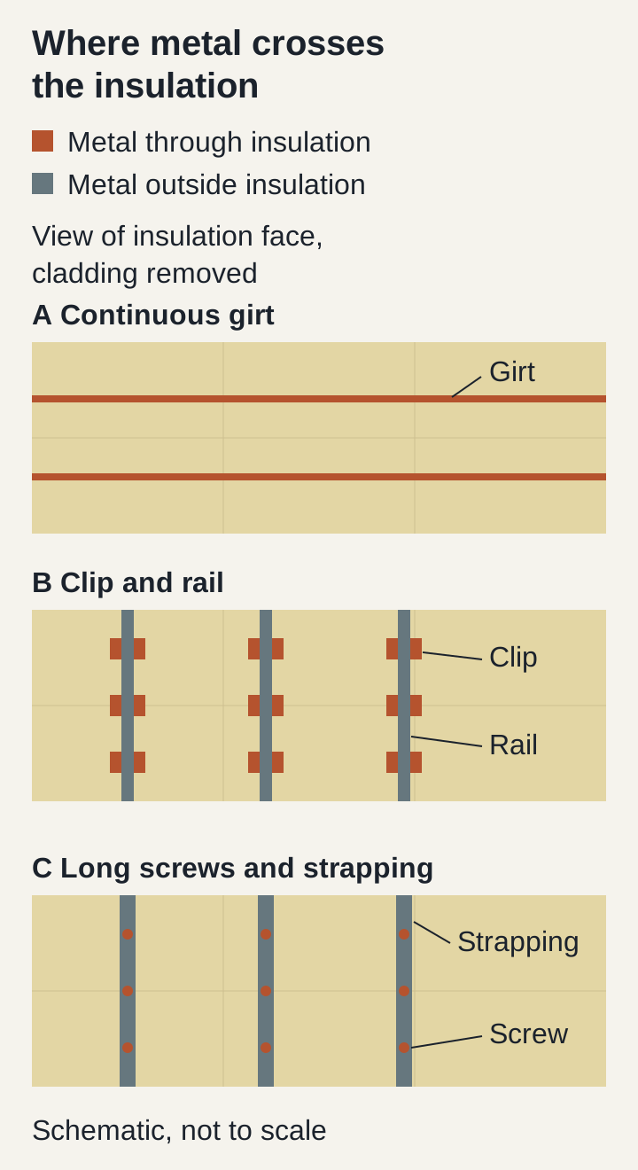
RDH describes continuous girt systems as the predecessors of clip-and-rail systems and says they “do not perform nearly as well thermally”; it does not typically recommend horizontal or crossing Z-girts because of the amount of thermal bridging. Clip-and-rail systems usually let only the clips penetrate the insulation, but in some designs the rail web also cuts into it, which degrades performance in a way similar to girts. Long-screw systems connect strapping or girts on the outside of rigid insulation back to the structure; the screws, strapping and insulation act together as a truss, and the guide describes them for light- to medium-weight cladding. It adds that they are best suited to low-rise wood-frame buildings with lower rainwater exposure, because a screw penetration through the sheathing membrane cannot be effectively sealed after installation; for mid- to high-rise buildings with greater exposure it typically recommends clip-and-rail systems whose clip fasteners can be sealed before the insulation is installed. Masonry ties are different again: the guide’s figure notes they give lateral support only, with veneer weight carried at the base.
Swipe or scroll horizontally to view all columns →
| Strategy | Where metal crosses the insulation | Structural evidence to request | Thermal evidence to request | Interface checks |
|---|---|---|---|---|
| Continuous girts through the insulation | Along the full length of each girt | Girt, connection and back-up wall capacity for the actual cladding load | A model of the whole assembly including the girts, not the nominal value of the boards between them | Splices, corners, openings, drainage past horizontal members, metal compatibility |
| Discrete clips with outboard rails (source’s typical recommendation for mid- and high-rise walls with greater exposure) | At each clip; also along the rail if its web sits inside the insulation | All links from cladding to structure, deflection, anchorage, added supports at details | A model or χ-value for the same clip, fasteners, insulation thickness and back-up wall, with the real detail density | Adjustment range, shims, separation of dissimilar metals, insulation fit around clips |
| Long screws with exterior strapping (source scope: light- to medium-weight cladding, low-rise wood frame, lower rain exposure) | At each screw | Design or documented basis for this cladding weight, back-up wall and insulation | Screw material, layout and back-up wall matching the modeled case | Hitting studs or designed sheathing, membrane penetrations that cannot be sealed later |
Common mistake: Accepting a “thermally broken” clip system without checking where the rail sits. If the rail web is set into the insulation, the system behaves partly like a continuous girt.
Use the exterior cladding guide to confirm the cladding family itself is suitable before comparing how it is held up; on homes and smaller buildings, the Pacific Northwest siding guide compares siding materials by site exposure and maintenance.
Takeaway: Rank the options by the metal path through the insulation only after the structural evidence shows each one can carry the cladding.
How does the cladding load reach the structure?
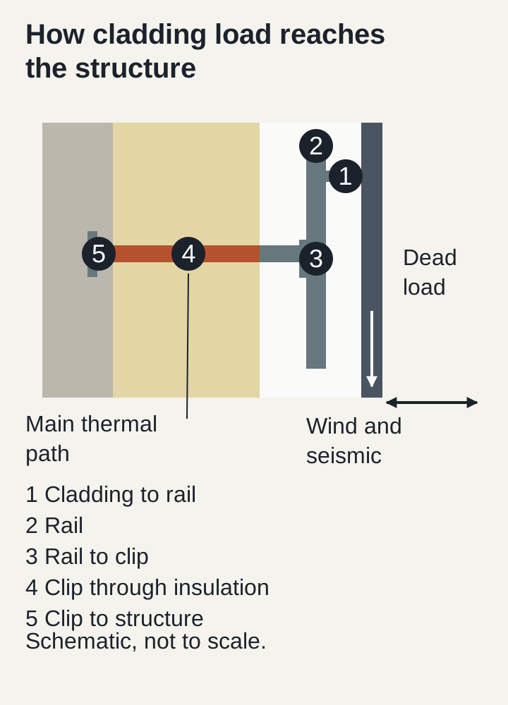
In a clip-and-rail system the load passes through five links, and every one needs structural evidence. RDH lists them as the connection between cladding and rail, the rail or girt itself, the connection between rail and clip, the clip that penetrates the insulation, and the connection between clip and structure. They act together to resist dead, wind and seismic load and to limit deflection.
- Cladding to rail
- Rail (sometimes two layers in a grid)
- Rail to clip
- Clip through the insulation
- Clip to structure
Several conditions change those links. Horizontally oriented cladding generally favors vertical rails, and vertically oriented cladding requires horizontal rails. Thin or brittle cladding may need closely spaced framing, which can call for an intermediate framing layer rather than more clips. Deeper insulation increases the load on the system through eccentricity, because the cladding sits farther from the wall. Where rails are stacked in a grid, RDH warns that clips nearest a point load can carry more than a uniform-spacing calculation assumes, so the calculations should account for it.
The design is typically undertaken by a structural or façade engineer working for the architect or the cladding manufacturer, and some systems are pre-engineered with manufacturer load tables. Record who produced the calculation or table and the conditions it assumes. On existing buildings, confirm what the clips will actually fasten into; the commercial renovation guide covers investigating concealed substrate before relying on it.
Takeaway: Ask for evidence covering all five links, not only the clip’s own rating.
What does a low-conductivity clip actually change?
A lower-conductivity clip reduces the heat flow at each penetration; it does not reduce the number of clips the structure needs, and it does not prove load capacity or fire performance. RDH notes that less conductive clips and fasteners make a system more thermally efficient, and that this helps because more clips are inevitably needed at details.
The same guide says the strategy is to space clips as widely and use as few as possible while still meeting structural requirements, with maximum spacing typically governed by wind load and rail stiffness. Wider spacing is not free: it can require stronger, larger rails or make some claddings hard to attach. Do not ask an installer to drop clips to improve a thermal number; that is a structural design decision.
For fiberglass clips that form part of the load path, RDH points out that the adequacy of the screw connection into the fiberglass matters and that fire performance of these systems should be verified. A material claim from the manufacturer is a declared property; the How We Review Materials page explains why this site keeps declared values separate from independently verified performance.
Swipe or scroll horizontally to view all columns →
| Claim you may see | What it supports | What still has to be shown |
|---|---|---|
| Low-conductivity clip material | Less heat flow per clip, other things equal | Structural capacity, connection detail, fire evidence for the assembly |
| Isolation pad or thermal washer | A local reduction at that contact | Whole-assembly thermal result; it does not turn a girt into a clip system |
| Fewer clips per area | Less metal through the insulation in the clear field | Rail size, deflection and the extra clips at details |
Takeaway: Treat low conductivity as one input to the comparison, not as proof that the system fits the wall.
How should thermal model results be compared?
Compare thermal results only when they describe the same back-up wall, the same exterior insulation thickness and the same nominal insulation value, and then add the extra supports the real facade needs. RDH’s own comparisons were produced with calibrated three-dimensional thermal modeling, using the same assumptions, boundary conditions and material inputs for every system. It warns that manufacturers’ published data needs care when compared.
RDH’s spacing and thermal comparisons assume an unobstructed “clear-field” wall. Real walls have windows, penetrations, cladding joints, flashings, trims and floor-line separations, and each of these adds supports beyond the clear-field pattern.
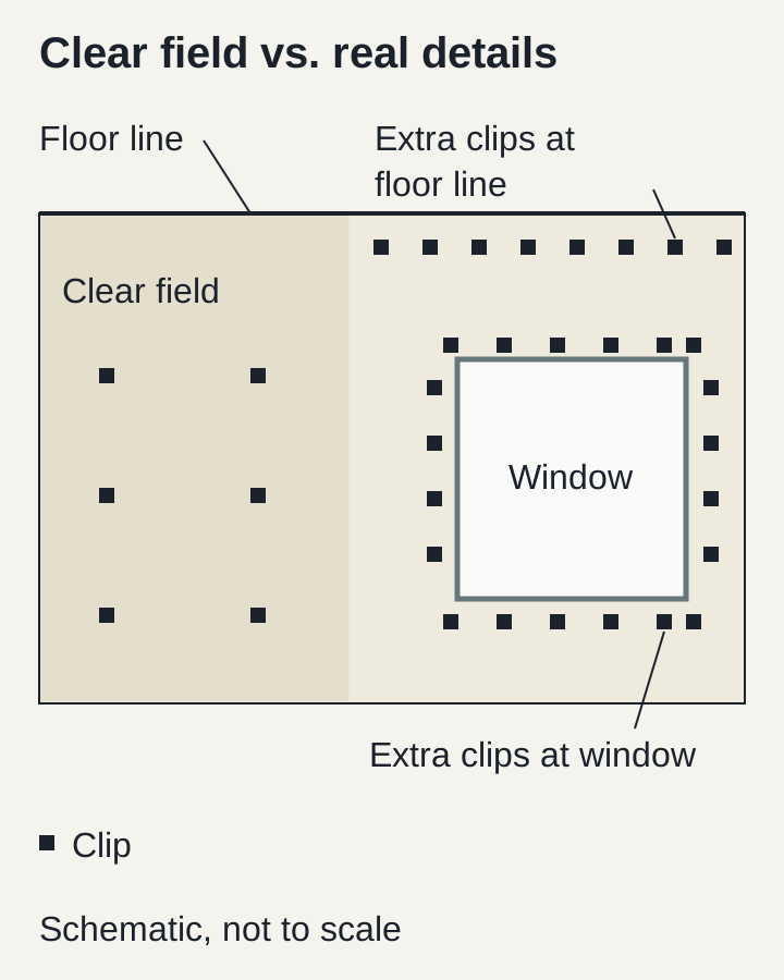
One way to carry those extra supports into the calculation is the clip χ-value (chi-value): the additional point heat flow through the wall caused by one clip, compared with the same wall without it. RDH says χ-values can be used with an average tributary area per clip, but only for assemblies with the same back-up wall type, exterior insulation thickness and nominal insulation value as the modeled assembly. A value calculated for a concrete wall does not transfer to steel studs.
Insulation retention matters too. Gaps between or behind insulation boards degrade thermal performance, and metal insulation fasteners add their own bridges, so RDH advises using them sparingly. Ask whether the model includes them.
Swipe or scroll horizontally to view all columns →
| Comparison check | Record |
|---|---|
| Same back-up wall, insulation thickness and nominal value in every result compared | Yes / no, with the modeled assembly named |
| Clear field only, or whole wall including details | State which |
| Model source, date, boundary conditions and material inputs | From the report, not a sales sheet |
| Insulation fasteners and board fit included | Yes / no |
| Output units and whether the value is for a clip, a wall area or the whole wall | As stated in the report |
Common mistake: Lining up χ-values or “effective R” figures from different manufacturers without checking that each was modeled on the same back-up wall and insulation thickness.
The building envelope guide explains how the thermal layer fits with water, air and vapor control across the whole wall.
Takeaway: A thermal number is only comparable when its assembly matches yours and its scope includes the details.
Which interfaces need checking before the wall is closed?
Most attachment problems are fixed cheaply before the cladding goes on and expensively after. Check five interfaces: what each support fastens into, how penetrations through the air and water barrier are handled, how dissimilar metals are separated, how tightly the insulation fits around supports, and how much out-of-plane adjustment the system provides. When the cladding joints stay open, that membrane remains in the weather after the panels are on. The open-joint rainscreen review separates that long-term exposure from temporary uncovered time and names who owes each missing proof before the wall is closed.
Swipe or scroll horizontally to view all columns →
| Interface | What to confirm | Why it matters |
|---|---|---|
| Back-up wall anchorage | Supports land on concrete, studs, designed sheathing or a designed intermediate support | With steel studs and gypsum sheathing, RDH says attachments must go into the studs; where studs cannot be placed behind each support, intermediate supports need specific structural design |
| Membrane penetrations and sequence | When supports are installed relative to the sheathing membrane and how each penetration is sealed | RDH notes a long-screw penetration cannot be effectively sealed after installation, unlike clips or girts installed before the insulation, and for that reason places long screws on low-rise wood-frame buildings with lower rain exposure |
| Dissimilar metals | Separation between, for example, aluminum rails and steel clips or fasteners | RDH notes these are typically isolated to prevent galvanic corrosion |
| Insulation fit and retention | Boards tight to the back-up wall and around each support; retention method stated | Gaps or displaced boards reduce thermal performance |
| Adjustability and tolerance | Out-of-plane adjustment range and how shims are used | The cladding plane has to be achievable on an imperfect wall |
Coastal exposure adds corrosion questions that a thermal comparison does not answer; the coastal construction guide covers salt exposure and concealed fasteners. Keep the cavity draining and drying as described in the moisture-control guide, and protect exposed insulation during wet-season installation using the sequencing advice in the rainy-climate construction guide.
Takeaway: Record the interface details on the same page as the thermal and structural evidence so none of them is approved in isolation.
Copy the attachment evidence record
The record below keeps the thermal, structural and interface evidence for one wall zone together. Copy it once per wall type or zone; leave fields blank until a document fills them. The status words are this site’s editorial convention, not a compliance or safety rating.
Swipe or scroll horizontally to view all columns →
| Field | Evidence or value | Source document and date | Responsible party | Status |
|---|---|---|---|---|
| Project and wall zone | ___ | ___ | ___ | Requested / Matched / Mismatch / Unresolved |
| Cladding type, weight and orientation | ___ | ___ | ___ | ___ |
| Back-up wall and anchorage target | ___ | ___ | ___ | ___ |
| Insulation material, thickness and nominal value | ___ | ___ | ___ | ___ |
| Attachment system, version and materials (clip, rail, fasteners) | ___ | ___ | ___ | ___ |
| Rail position relative to insulation | ___ | ___ | ___ | ___ |
| Clear-field layout and added supports at details | ___ | ___ | ___ | ___ |
| Insulation retention method | ___ | ___ | ___ | ___ |
| Structural basis (calculation or load table) and its conditions | ___ | ___ | ___ | ___ |
| Thermal model or χ-value: assembly, scope, boundary conditions, date | ___ | ___ | ___ | ___ |
| Membrane penetrations and installation sequence | ___ | ___ | ___ | ___ |
| Metal compatibility and exposure | ___ | ___ | ___ | ___ |
| Fire evidence matching the actual assembly | ___ | ___ | ___ | ___ |
| Adjustment range and tolerance basis | ___ | ___ | ___ | ___ |
| Open items and revision log | ___ | ___ | ___ | ___ |
Mark a field Mismatch when the evidence describes a different assembly — another back-up wall, insulation thickness, cladding weight or clip — and Unresolved when no document covers it yet. Neither should be read as approval.
Takeaway: A complete record shows which evidence matches the proposed wall and which still needs the design team.
When this comparison does not apply
This page helps organize evidence; it does not replace project design. Do not use it to:
- choose clip spacing, screw size, rail section or allowable loads — those come from the attachment designer;
- rank current products or say one system is right for every office building;
- shortlist long screws for an office tower because they put fewer metal crossings through the insulation — the source describes them for light- to medium-weight cladding on low-rise wood-frame buildings with lower rain exposure;
- decide which code edition, fire classification or energy requirement applies — confirm these with the design team and the authority having jurisdiction;
- predict energy savings or an effective R-value — the RDH modeling dates from 2018 and is a method reference, not a test of current systems;
- design masonry veneer support, shelf angles or other gravity supports.
See the editorial policy for how this site handles sources and limits.
Takeaway: Use the matrix and record to ask better questions; leave the answers to the people who sign the design.
Take the record to the project team
Keep the evidence matrix and ask the project design team for drawings, current manufacturer documents and unresolved inputs. Bring the completed record to the next design or submittal review, and ask the team to replace every blank or Mismatch with a matching document or a named decision.
- Ask the architect or envelope consultant for the wall-type drawings, insulation specification and details at windows, joints and floor lines.
- Ask the attachment designer or manufacturer for the current structural basis and a thermal model or χ-value for the matching assembly.
- Ask who owns each open item and when it will be resolved.
The construction management guide explains how submittal responsibilities are usually assigned. When comparing bids, the contractor bid comparison guide shows how to check that each proposal prices the same attachment scope, including the extra supports at details. Return to the Building Materials hub for related wall guides.
Takeaway: The next step is a filled record, not a product choice.
Common questions
Do screws through exterior insulation reduce the wall R-value?
Yes, each metal screw is a thermal bridge through the insulation. RDH says the effect in long-screw systems depends on the back-up wall, the fastener type and the fastener spacing. Metal insulation fasteners add further bridges, so ask for a model that includes the actual screws.
Is there a realistic way to fasten cladding that doesn’t include some thermal bridging?
Not among the strategies RDH reviews: every system must be attached back to the structure, so something crosses the insulation. The practical goal is fewer, less conductive crossings that still meet structural requirements, verified with a model of the actual assembly.
Does a shelf or base support change what the screws have to carry?
It can, but only the structural design can say how load is shared. RDH’s masonry example separates the roles: ties give lateral support while veneer weight sits on the base. For any other system, ask the designer which elements carry gravity load and which resist wind.
Does thicker exterior insulation change the cladding support design?
Yes. RDH notes that greater insulation depth increases the structural load on the attachment system through eccentricity, because the cladding sits farther from the wall. Thermal values also change with insulation thickness, so both evidence sets must match the thickness proposed. Enter the same thickness in the structural-basis and thermal-model rows of the evidence record, and mark either row Mismatch if its document assumes another thickness.
Do thermal break pads fix a girt system?
They reduce heat flow at the contact they separate, but RDH still does not typically recommend horizontal or crossing Z-girts because of the remaining bridging. Judge the result from a whole-assembly model that includes the pads, not from the pad alone, and note in the thermal-model row of the record whether the pads were modeled.
Can a long-screw system be used on an office tower?
The source does not point that way. RDH describes long-screw systems for light- to medium-weight cladding and says they are best suited to low-rise wood-frame buildings with lower rainwater exposure, because the screw penetrations through the sheathing membrane cannot be effectively sealed afterward. For mid- to high-rise buildings with greater exposure it typically recommends clip-and-rail systems whose clip fasteners are sealed before the insulation goes on. If a long-screw proposal appears for a taller building, ask the design team for the basis and record the answer in the membrane-penetrations row.
Are fiberglass or plastic clips automatically acceptable for fire?
No. RDH says fire performance of fiberglass clip systems should be verified, and that the screw connection into the fiberglass matters where the clip carries load. Ask for fire evidence that matches the complete wall assembly, and record the document and the assembly it covers in the fire-evidence row of the record.
Sources and limitations
Technical statements on this page were checked against RDH Building Science, Cladding Attachment Solutions for Exterior-Insulated Commercial Walls, April 2018, version 4 (PDF reviewed October 11, 2026; printed pages 1, 3, 5–8, 11, 21–23, 27–29, 37–38, 42 and 44–45). The bulletin focuses on thermal performance and covers structure, fire and constructability only briefly; it directs readers to manufacturers for performance and testing data. Its modeled percentages are not repeated here because they describe 2018 models, not current products.
The comparison matrix, interface table and evidence record organize the review criteria from that RDH engineering bulletin for project submittal verification. The first two questions in Common questions address recurring practitioner questions from public GreenBuildingAdvisor discussions (2015 and 2025); the remaining questions summarize key boundaries from the same RDH reference.
Product documents, codes and modeling practice change. Use current documents for the specific system and qualified professionals for project-specific structural, fire, energy and code decisions.
Published October 11, 2026.
Related articles
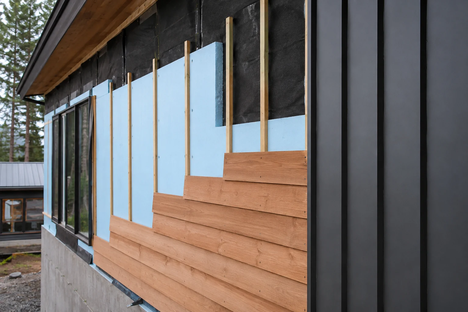
Rainscreen Wall Systems: Design and Construction Guide
Choose drained, ventilated or engineered pressure-controlled walls first; keep the selected system's drainage and ventilation outlets clear.
Read article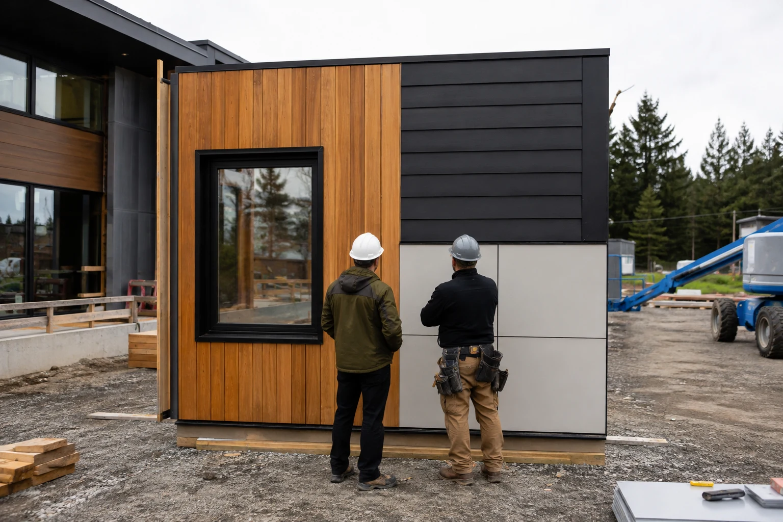
Exterior Cladding Guide for West Coast Buildings
Compare complete cladding systems before sample prices: support, drainage, attachment, fire evidence and maintenance access can change the choice.
Read article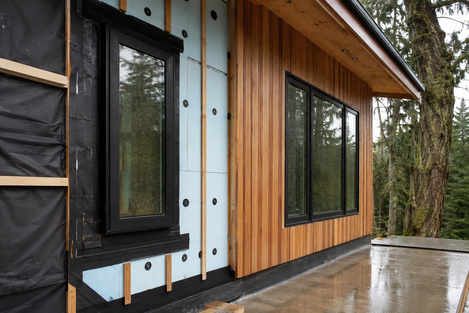
Building Envelope Basics for West Coast Projects
Trace water, air, vapor and thermal control across openings and joints; assign missing details before finishes hide paths for leaks.
Read article